Lockdown in NZ across April-May meant no CNC laser cutting and folding (well unless you had your own serious production shop in your garage!) so I put the final design tweaks on the go-slow as I couldn’t get anything built.
However that did give me time to get things tweaked and played around with. In good tech style, left it to the last minute…
Refining
I spent the final lockdown weekend refining my designs, getting positions of every thing correct, ensuing bolt holes were in the right place [or so I thought]. After fighting with some of the nuances of Fusion 360 I got there. It took an extraordinary amount of time (I reckon an easy 16 hours to remeasure/redraw things) especially after finding minor errors in datums which lead to lovely cascading errors. Finally I had a whole set of DXF’s to go off to the laser cutters.
Design Change: Swapped motor/push rod orientation.
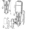
One of the things I wanted to do was swap around the side the push rod arcs from – instead of the on the edges in the centre. This would both (a) more closely match the radius of seat flaps and (b) potentially keep all the stresses along the spine of the seat. It was a big change to the design, and caused quite some consternation making sure I had things in the right position after the swap.
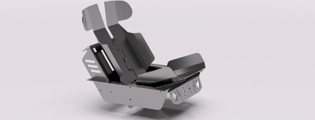
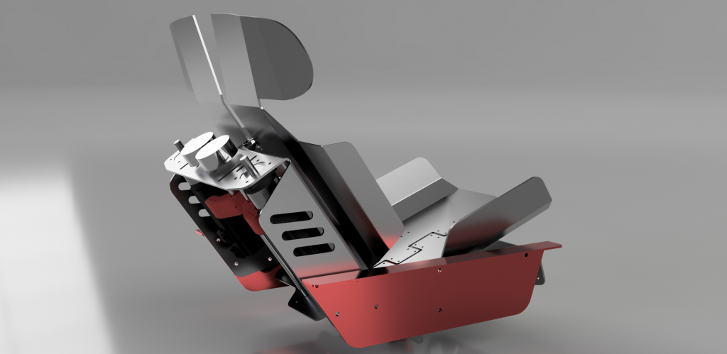
Ready to go
After a few weeks of umming and ‘ahhhing I pulled the trigger on getting the designs done. I sent it off to my guys with “I hope I got the k-factors right?” I came back with a glowing report card and a “well that looks awesome”. A production time of a week later was made the clock started ticking. In the meantime did a few renders to show what the seat looked like.
Parts arrived !
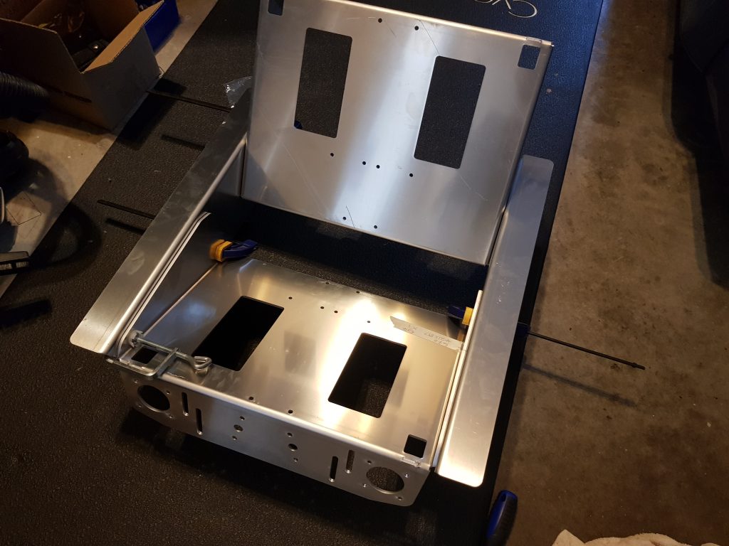
As is everyone’s new world in lockdown the random unexpected highlight of the day is a courier vehicle arriving. A few days earlier than the estimated production date a truck pulled up with my parts made :
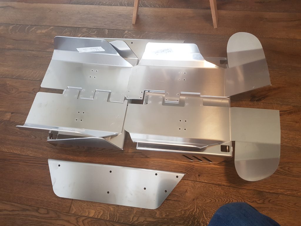
That evening I mocked it up to get a sense of what it was going to look like and make sure my design was on the right track :
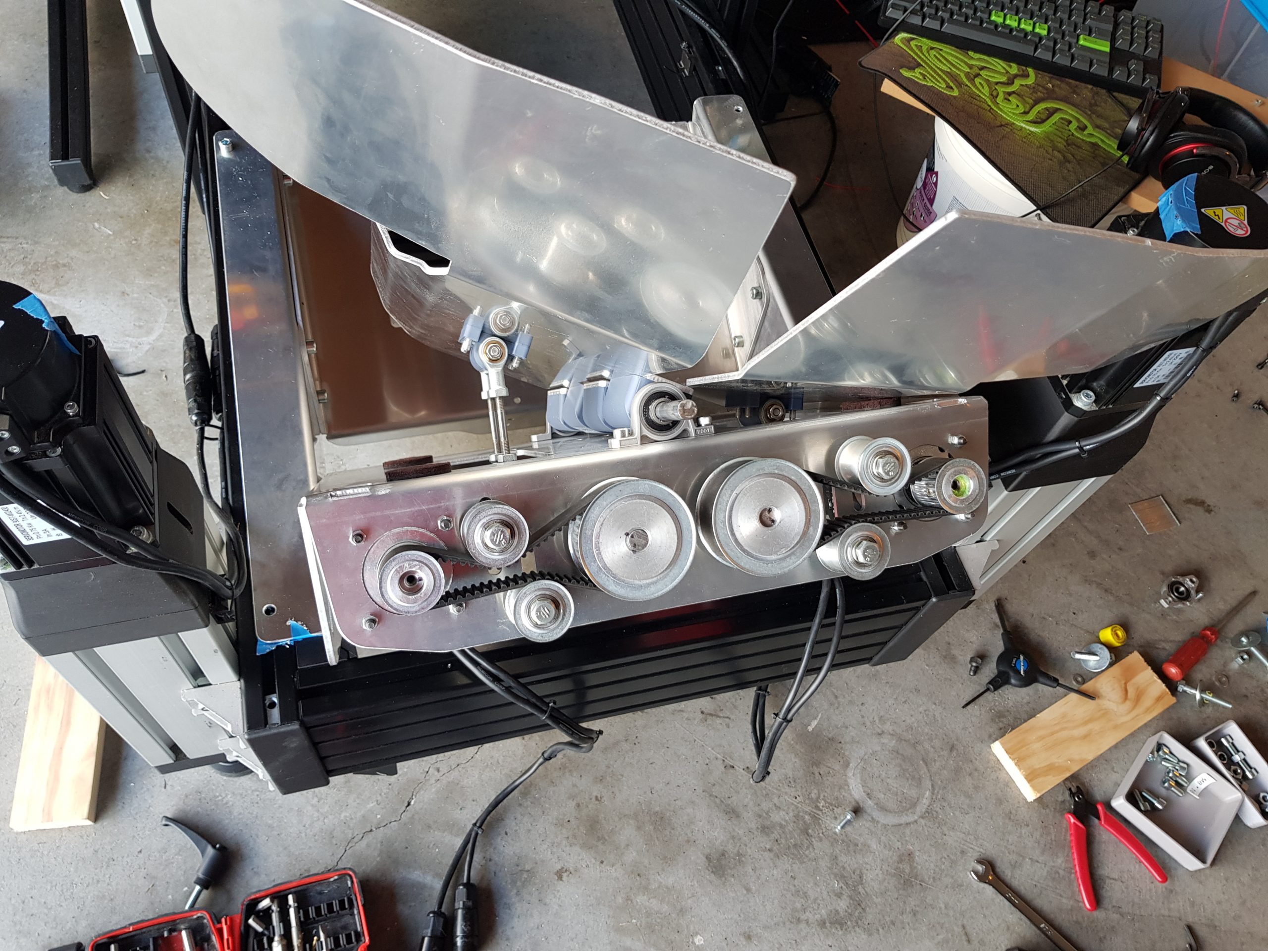
The build
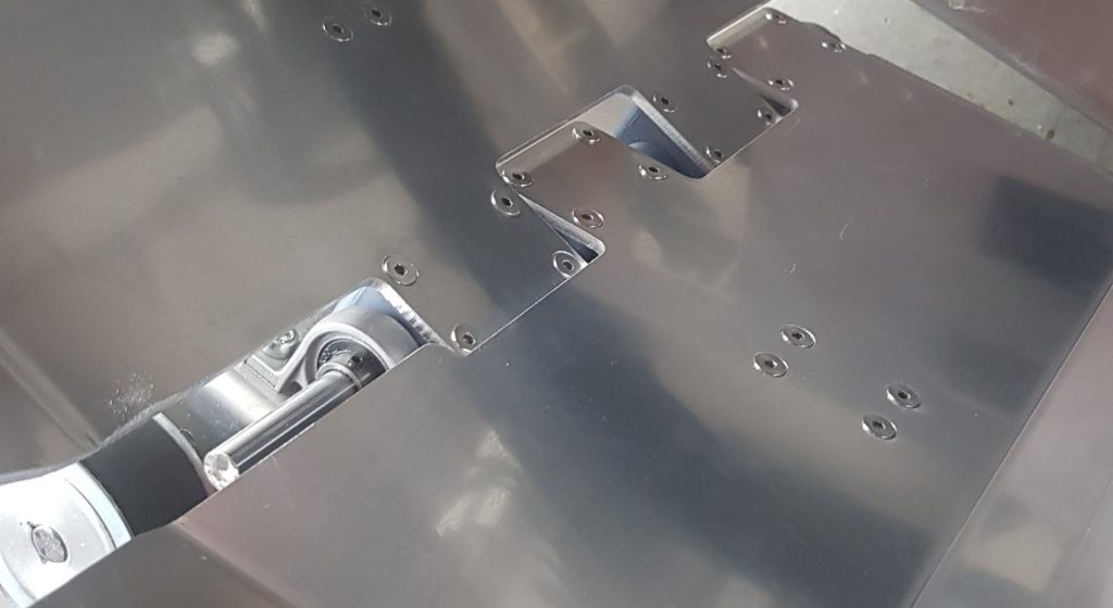
The weekend rolled around with my other half flat tack all weekend, that meant garage time – couldn’t have timed it better. First job was to test assemble/fit items. Two problems immediately discovered (1) I’d somehow missed in the “convert to flat pattern” process that the holes on the side of the bottom bracket weren’t there and (2) I hadn’t actually mesured my sim rig properly width wise and made the side rails slightly too short – wasn’t the end of the world and could fix (1) and live with (2).
What tools did I use?
This is where the “how DIY friendly is this” comes to play. It’s not the parts, it’s all the tools you need
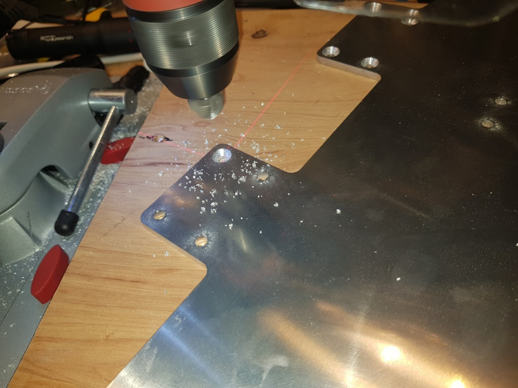
- Counter sink all holes on seat flaps in the drill press note: I didn’t think there was any use for the digital depth read out uptil now and then it was awesome; 29.8mm depth, over and over and over again. Perfect !
- Drill and deburr holes on chassis rails that weren’t laser cut (ideally calipers/ruler to ensure accuracy) with clamps to keep it together using a cordless drill
- File then smooth edges (then used an orbital sander)
- Mark with a holepunch then drill locating holes for chassis rails onto chassis
- Using a hack saw cut 12mm rod to size, file end smooth
- Drill locating holes for grub screws (use a metal score/punch to locate)
- Drill and Tap KFL001 clamps for M5 grub screws
- Assemble Pillow block bearings with allen keys and socket/spanners
- Hammer in 6mm shafts into pushrod arms
- Install servo drives, main shafts and main pulleys using allen keys/sockets
- Install belt using fingers
- Tighten up idlers using spanner and socket wrench
- Install flaps on hinge blocks that you’ve 3d printed with ABS/ABS+ or NylonX which means you will have built a simple but butt ugly highly effective enclosure
- Mount to seat
- Install seat in frame
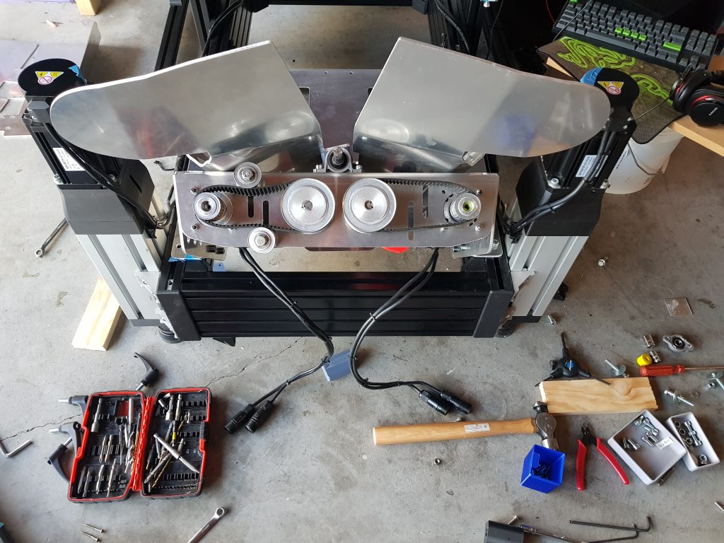
Getting it all together

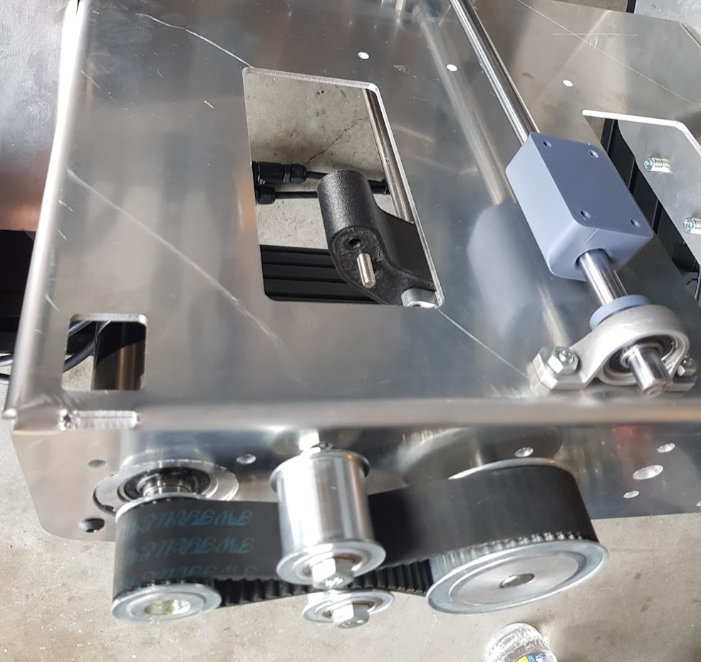
Build Hints: Removing play
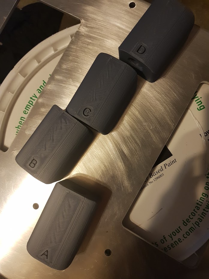
Getting a tight system is critical for getting detail feedback – the more play/slop in things like hinges – the less detail is transmitted – it’s taken up play instead of moving things. To this end as I eluded to in a previous blog post I designed a hinge comprising two bearing carriers, a 12mm rod, 3d printed (ABS) hinge blocks that would mount onto the seat flaps hinge fingers.
My goal was to get silky smooth movement with no slop. It was all a bit of a gamble but surprisingly all worked. I just had to do a few test prints on the hinge blocks to get the right clearance on the 12mm shaft – too tight and they wouldn’t slip/move, too loose and there would be play. 12.6mm ID seemed to be the trick – given the way I had to orient the parts for printing.
Build Hints: Think about how you assemble something
It’s not just good enough to get something mechanically working, it’s important to be able to actually pull it apart and put it back together (ideally quickly). Two things I specifically did to help matters on this build –
- I added holes at the top of the brackets, right behind the 4th servo bolts….. I wonder why? There’s no way you can get at the bolt otherwise.
- Because I was a bit lazy on drawing up the hinge fingers they weren’t all the same dimensions. So my laziness turned into extra work by adding their build order into the prints themselves. Get it right first time folks…
- Ensuring there was enough gap for bolt heads between the chassis rails and the chassis…
And after assembly, what does that mean? You guessed it
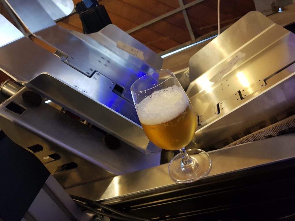
Testing time !
So….?
It’s freaking awesome. What more can I say ? It complements the SFX-100 platform massively. It is *way* more physical when you’ve got the intensity turned up. It accentuates/reinforces the g-loading a car gets going through a corner and is incredibly reactive.
What’s next?
- Well naturally I want to get the bottom panels working, why aren’t they ? Starts with C, ends with 9 and is a right downer on international shipments. I’m missing the 4th servo – a new one is on it’s way from China (theoretically…) once that’s done I can assemble the bottom piece
- Seat flap ‘stops’. I originally thought I’d want home position to be angled backwards, in practise doesn’t work – so need to maintain a parallel/home start position from the brackets.
- Contoured foam & upholstering the seat panels – there are some pointy bits that need to go
- I might see if I can find some slightly better rod ends
- Adding further support blocks for the main push shafts – removing flex from the system
- Adding a capture plate for the idlers – removing flex from the system.
- Surface finishing. That is going to take forever. Will it happen? will it be left? Is this truly like a racecar where function comes before form?

[…] not, well not yet anyway. Could potentially be in future – there are a number of areas that require specialist tools (see half way down that post) and fabrication skills, along with potentially some Fusion 360 […]
Well done Rowan. Incredible what you have achieved. Love a good Pilsner.
Cheers Adrian !
This is truly an awesome development thus far Rowan..!!! The amount of progress that you’ve accomplished during this project is outstanding. I’m curious if you’re likely to complete your build process any further, as it appears you haven’t posted an update for some time yet. Do you have additional details to add going forward? Thanks for all the awesome works thus far as it is very encouraging.