Any of the works related to “@steely’s G-Seat” is Copyright 2020, Rowan Hick released under the Creative commons license Attribution-ShareAlike 4.0 International (CC BY-SA 4.0) . Read here for more details of what you can and can’t do, along with my intent.
The problem
If you’ve been following along one of the things you will have heard/read is that I’ve struggled with the actual seat itself. The “powerpack” is attached to the seat, which is great for retrofitting to a seat, however once you have 4 seat panels (2 power packs) the seat itself becomes quite redundant – the powerpack is on the outside of the seat, the flaps are on the inside of the seat so the seat itself is really just the chassis holding things together.
But is it any good at that? No. It’s got lots of irregular curves so it’s hard to mount things to. It’s uncessary weight. They flex a little and hard to work around. To get any width across the shoulders you must have your seat flaps quite far forward. Don’t even get me started on the bottom mounting! You start weighing up the cons and there’s not many pros.
The solution
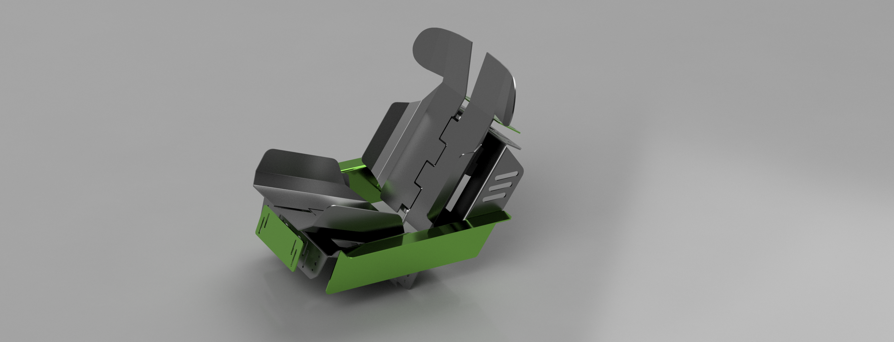
So why not get rid of the seat itself and make something purpose built?. I was looking quite heavily at my problem and then had the epiphany – get rid of the seat, just do the whole lot in folded aluminium.
Advantages
- It’s stiff – 4mm folded aluminium is nice and strong, this increases precision and reduces any noise.
- It’s modular– keep the overall width to work inside a 500mm chassis rail width and anyone who has an 80/20 style sim rig could potentially adapt it
- It looks rad – c’mon who doesn’t to make their rig look better.
- It’s repeatable – well, if the brackets are all a fixed dimension, then it would be easy for someone else to follow along
Disadvantages
- I’ve got to take the current seat to the dump
- It may not look race car enough 🙂
- Shit if anything went wrong with 240v, well, there’s a lot more conductive surface…
The design process
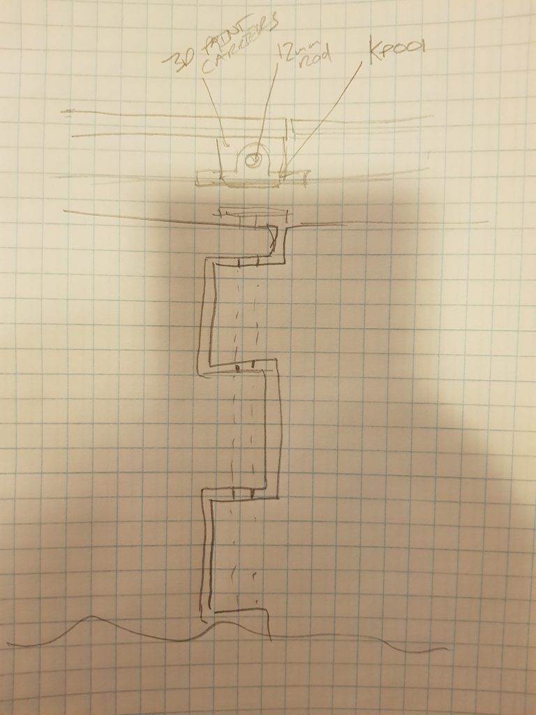
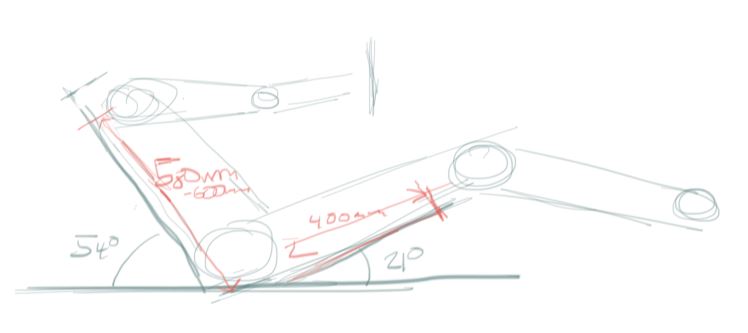
Usually this involves lots of sitting in the garage looking at the rig – visualising what I’m trying to acheive and get some rough dimensions. I did this then got out a piece of graph paper and started sketching..
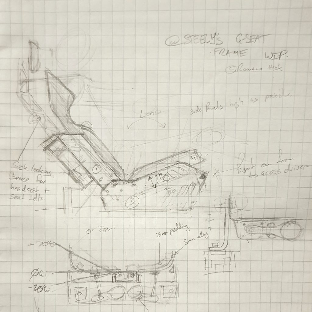
Seat mounting
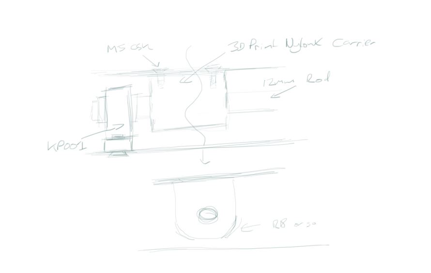
The first thing I had to work through was seat mounting. In the sketch above I was envisaging an “L” bracket on each side of the seat, but then I had an epiphany (one of many to come).. why not suspend the seat from the chassis rails themselves
This had an advantage that if I mounted them on delrin sliders, I could reasonably easily adjust the seat fore/aft and also have a very solid structure to mount the ‘seat’ to.
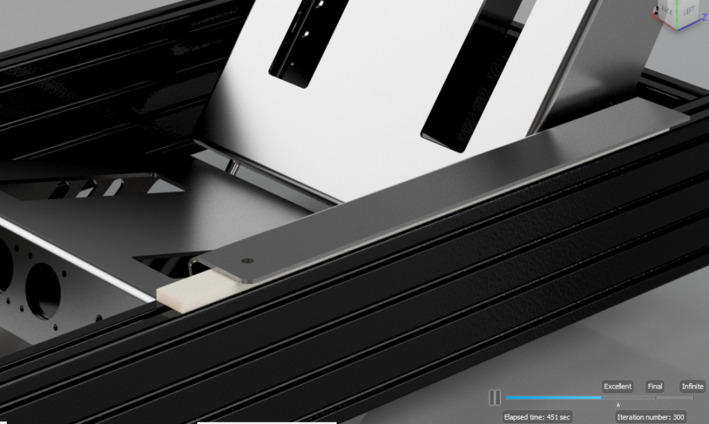
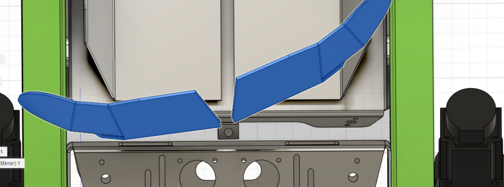
After that was sorted then came the task of starting to “work inwards” from my new reference points. I needed to redraw the brackets – I did a quick bodge job, to “rough in” the design starting with the rear one, redrew it and got it roughly the right angle. That meant I could do a quick seat of rear seat flaps to gauge I was visually on the right path.
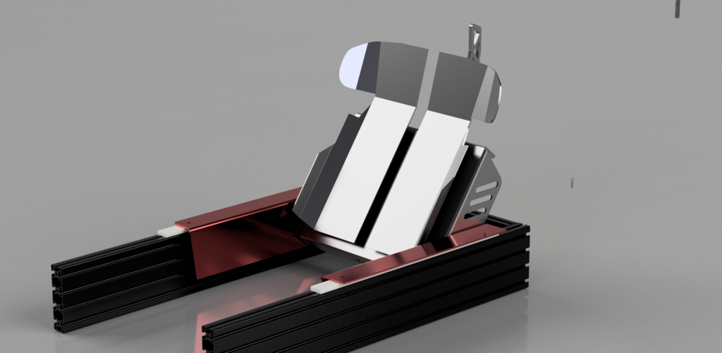
Why the red/green colour?
I want to end up having some accent pieces, so threw in a tribute to 90’s mountain biking and have played with anodising material types. Let’s see how prohibitive the cost is…
Starting to look good
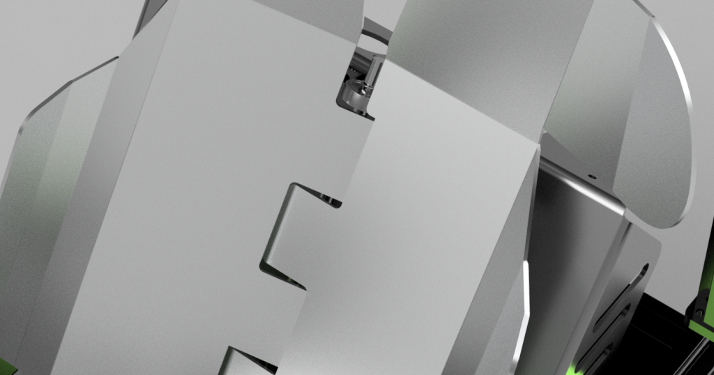
As always you make 80% of the progress in 20% of the time. Here’s where it really started to slow down. I drew in the bottom brace and flaps and then really hit the wall so to speak. While it looked good the problem was the flap hinge area.


Resolving my hinge problem
The prevailing wisdom is use an off the shelf set of hinges and you’re good to go. I however can’t make it this far and use a standard ole household butt hinge, or long piano hinge. No sire-bob we don’t things slick. Using my new found besty the KP-001 12mm ID pillow block bearing, I wanted a big solid industrial looking hinge with minimal, if not 0 play. Why? well any fine detail you don’t want taken up in the system – you want to feel it.
But that presented a problem, in that the offset of the two hinges started creating movement problems, where there would be a horrible little ridge in the spine of the seat and we don’t want that.
So let’s go back and look at flap design : There’s basically (what I’d seen) 2-3 or so different approaches of flap design. Like so
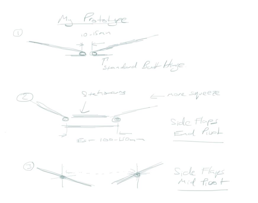
- Where the seat flaps pivot on their edge, central spine
- Where the seat flaps pivot on their edge, separated apart
- Where the seat flaps pivot in their middle
With my design (1) I was getting frustrated in that I couldn’t get nice movement in the centre. With the KP001 bearing the actual part of the flap had quite a distance to move through, creating potentially a ridge on the spine area. I walked away from the PC, and the next morning over coffee I had an a-ha moment. Why not make a single pivot. I sent my chicken-scratch sketch to the simfeedback discord to a resounding huh?
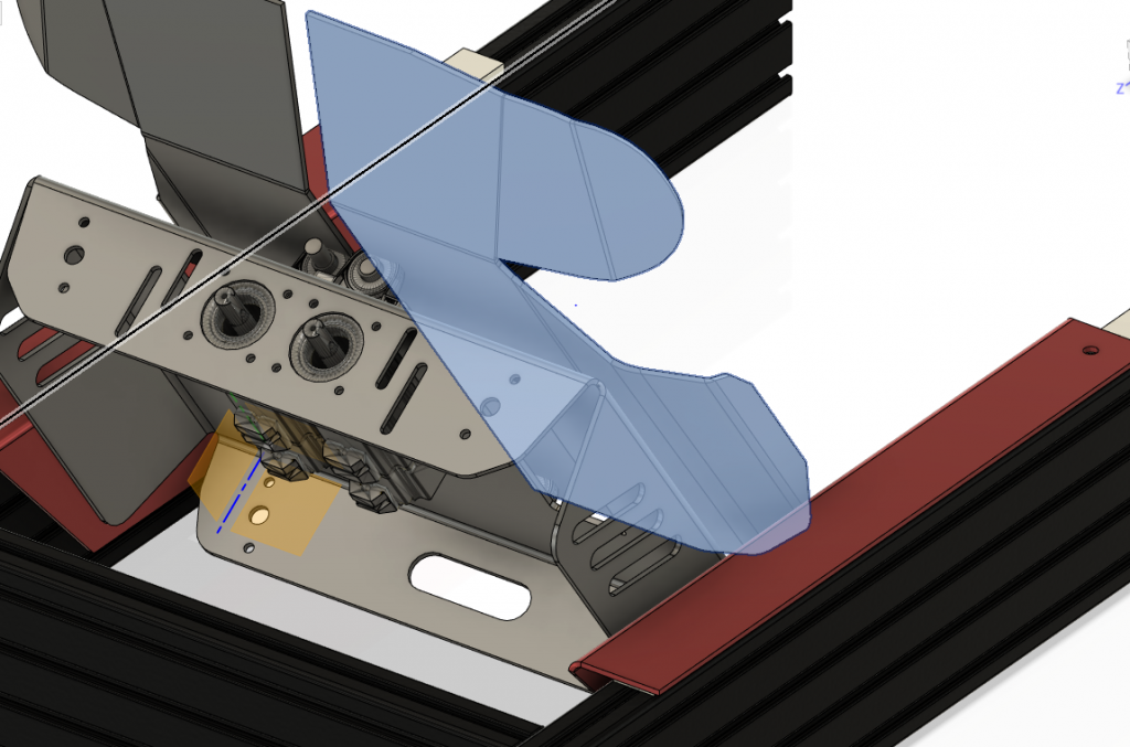
Much debate ensued as per normal; only answer is to try it. I sketched up the hinge mechanic in Fusion 360 and it passed the “my does that look good” test. With a layer of foam over it you would be none the wiser and it would feel very natural the roll off from +ve to -ve g’s
Removing idler flex
The load a full human puts on the seat is incredible. So much so I can see the flex in the system between the main shaft, the idlers. The astute will have noticed a little green plate – that’s meant to capture the idlers. Without this the idlers bend the 8mm bolts as there’s nothing supporting them. Likewise there needs to be a support in the middle of the main shafts to stop those bad boys from flexing as well.
Everything on hold
At this point I’d been racing to get this done for fear of my CNC guys being shutdown along with the rest of the country. Well… I didn’t make it in time. NZ went into lockdown and so to my CNC guys. So no getting this completed for at least end of April…
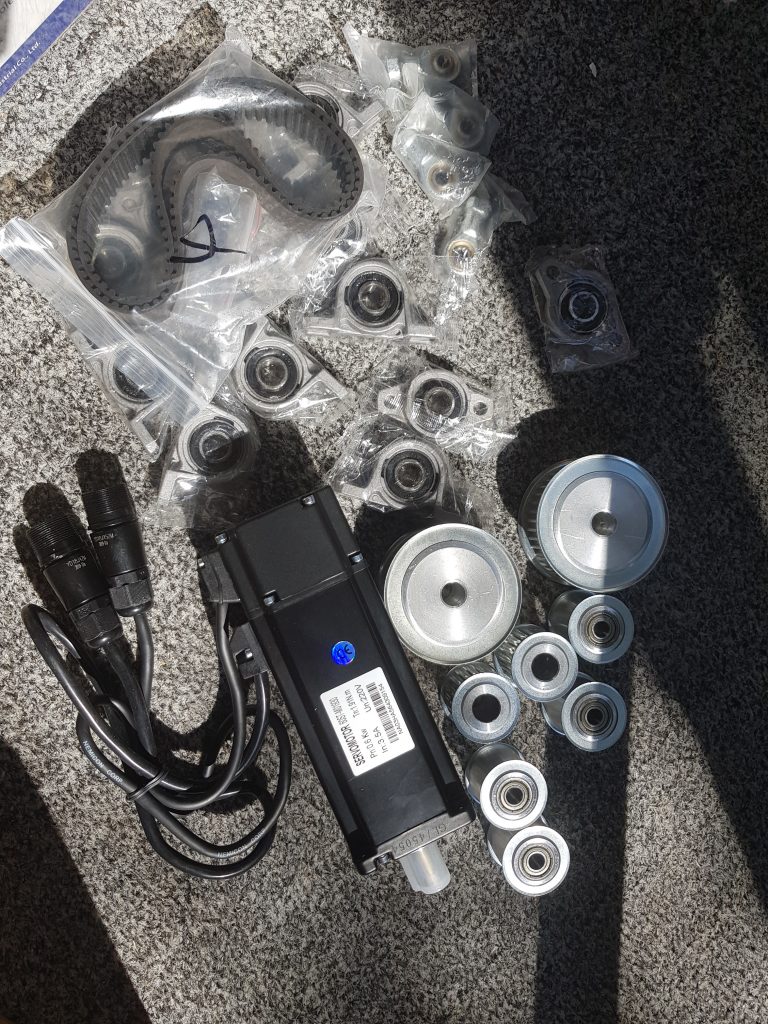
Doesn’t mean Aliexpress ain’t running
My parts for the bottom part of the seat kept trickling in. 1 servo seems to be taking the slow boat from China, but everything else I need has arrived.
Let’s complete the design shall we regardless
Well, post lock down, who know’s what’s running and how the world will be behaving, but let’s just assume for a second my cnc guys are back up and operational. So I’ll get the design completed.
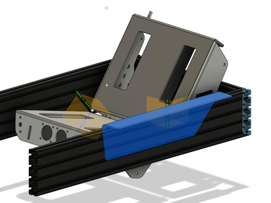
Next part after the hinge is getting the bracket angles and mounting sorted out.
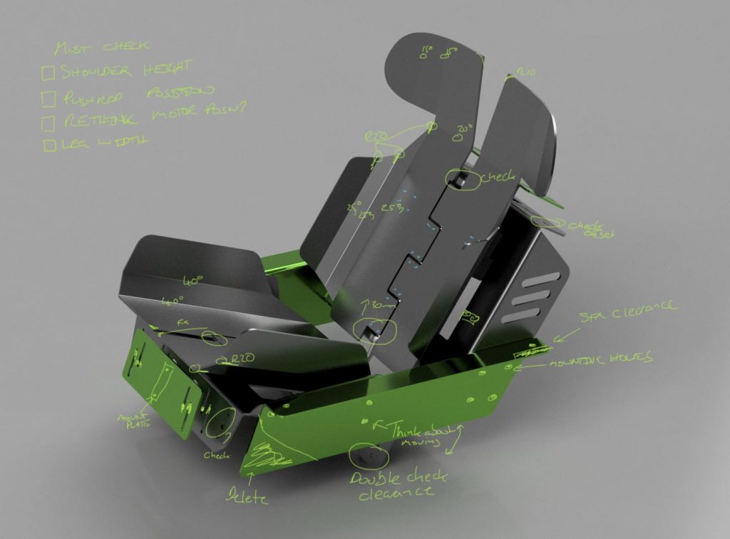
Before finalising everything I overlaid all the various notes on a rendering, I don’t really want to get to the end then found out I’ve missed something or got it in the wrong position.
There’s a tonne of hours going into this; the notes might give some indication of the kind of detail you have to work out :
New tool
You’ll also notice there’s lots of handwritten stuff on my pictures now. Well in my lockdown world I’ve wanted to go full digital, so got a little Wacom tablet, slowly getting used to it. Definite nice little addition to the virtual toolshed – makes it easy to annotate notes and sketch ideas, once you start getting used to it.
Next steps
There’s where we’ve gotten to today; I need to now sit down and recheck, redo, redraw until it’s perfect (or near enough). Only problem with CNC work is you have one shot…. and given the amount of aluminium in this. I don’t want to stuff it up !

Been following since first post.
Super excited to feel the final product.
My name is Hagay Farran I’m owner of SimRace.co.il
Israel’s only professional sim racing center.
We build bespoke simulators as well as give racing tution.
Would be proud once ready to represent you and your product in Israel, please keep me posted.
Thank you
Hagay
Thanks for the kind words Hagay ! Fully stoked to have a global audience 🙂 Will keep updated as to progress. Assuming it’s nice and repeatable then I could possibly look at supplying the “hard parts” being the actual aluminium frame/brackets all cut/folded to spec.
Hi rowan, my name is Cédric and I come from France. I followed your project from the beginning and then I started and built the sfx 100 thanks to the great work of the Simfeedback community. I’m very happy with it. I find your work great on gseat and I will start if you can offer the aluminum structure
Nice to meet you Cedric ! I will let you know when I get my first aluminium parts made and tested- hopefully this week coming the engineering shop is up and running again and I can get some made 😉 I’m still waiting for the 4th and final servo from China, it seems to be stuck in shipping.
[…] – it’s taken up play instead of moving things. To this end as I eluded to in a previous blog post I designed a hinge comprising two bearing carriers, a 12mm rod, 3d printed (ABS) hinge blocks that […]