I’m stubborn, I think this post will prove that.
Following on from my previous post https://www.rowanhick.com/2020/01/25/delving-into-the-world-of-g-force-cueing I switched up my approach and went for a full blooded AC Servo, retaining the same principle design.
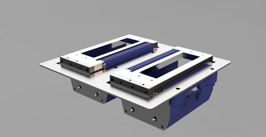
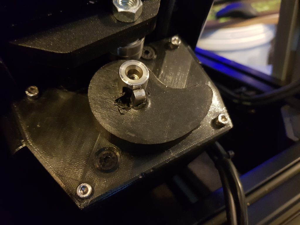
To help you visual what’s going on here, here’s a rendering of the two motor pods that would go on the back of the seat. Motors go in the cavities, and they push a cam that moves the flap
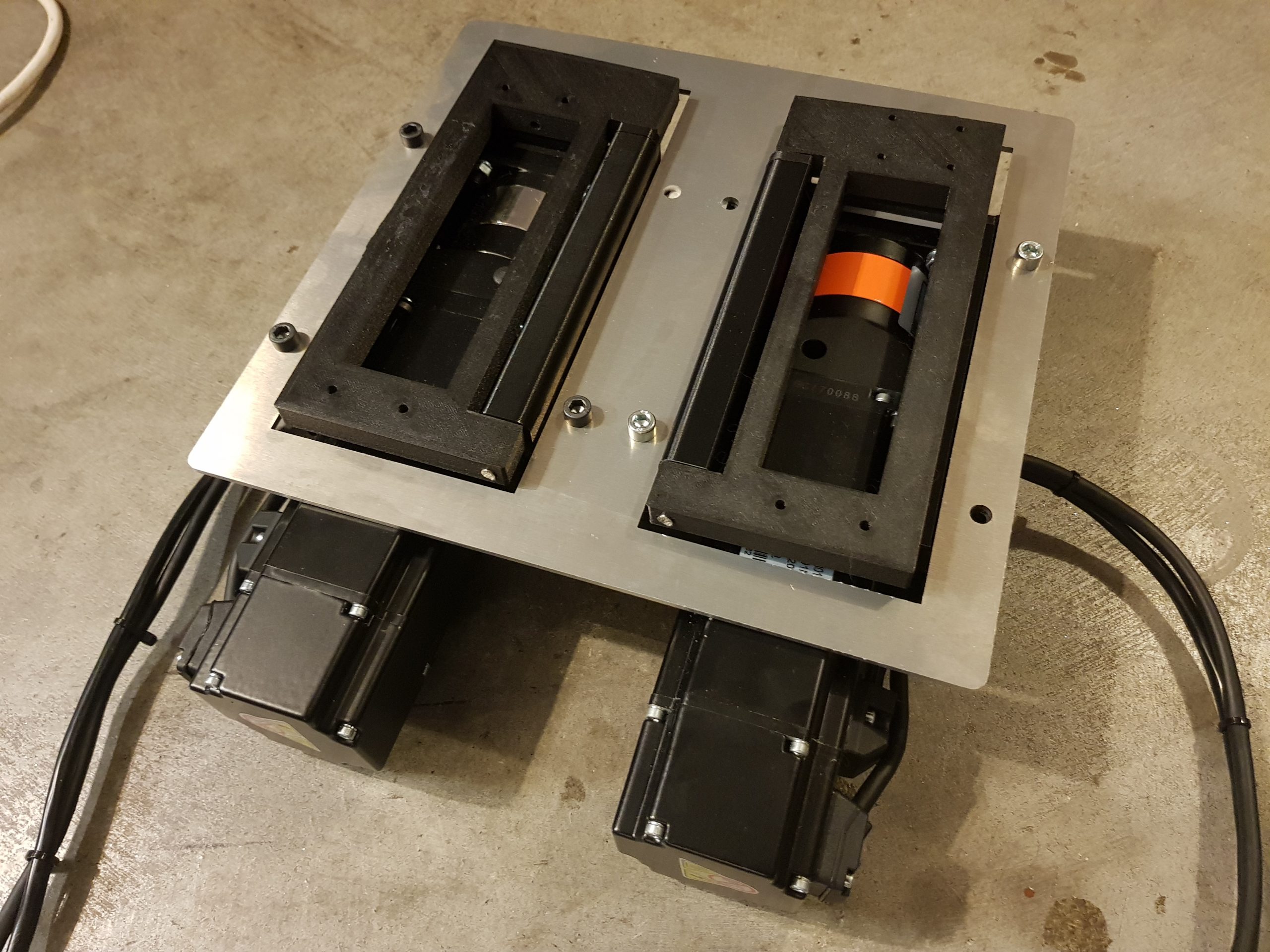
And here’s what they looked like at the final stage of this iteration.

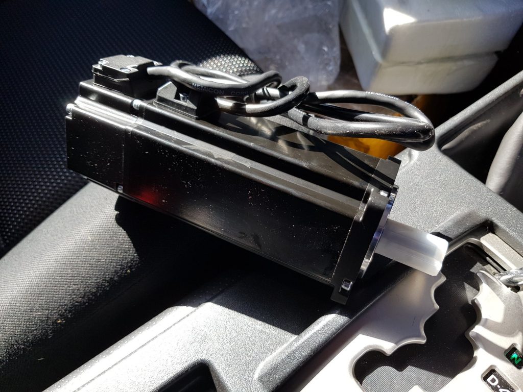
After a few weeks waiting (you know what it’s like for new parts) fiiinaaally my servos arrived. Of course like all interesting parts pickup from the post office I couldn’t wait to get home and unpacked it in the truck. Check out this cool new toy !
Let’s get it built
Part of my design goal was I wanted 3d printed parts as much as possible, it keeps the prospect of your home DIY person, being able to make parts without costly CNC outsourcing. So with his in mind I set out to to see if I could make 3d printed pieces work.
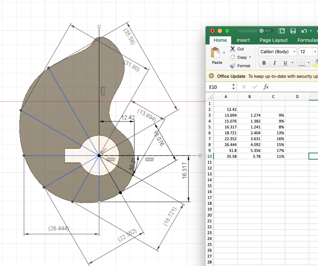
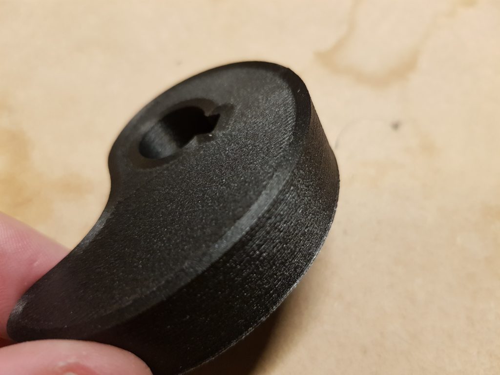
I started out with trying to design the cam; many, many iterations of trying to find out how to do it properly (mathematically) and then I just gave up and hacked it out – created a spreadsheet, divided up the cam by 12 segments, did a formula to increase the radius at each point appropriately, plotted it out and bingo, I had a cam.
Probably a good dozen or so prints I finally got one where the movement was just right and the flaps would “self close” when the motors powered off.
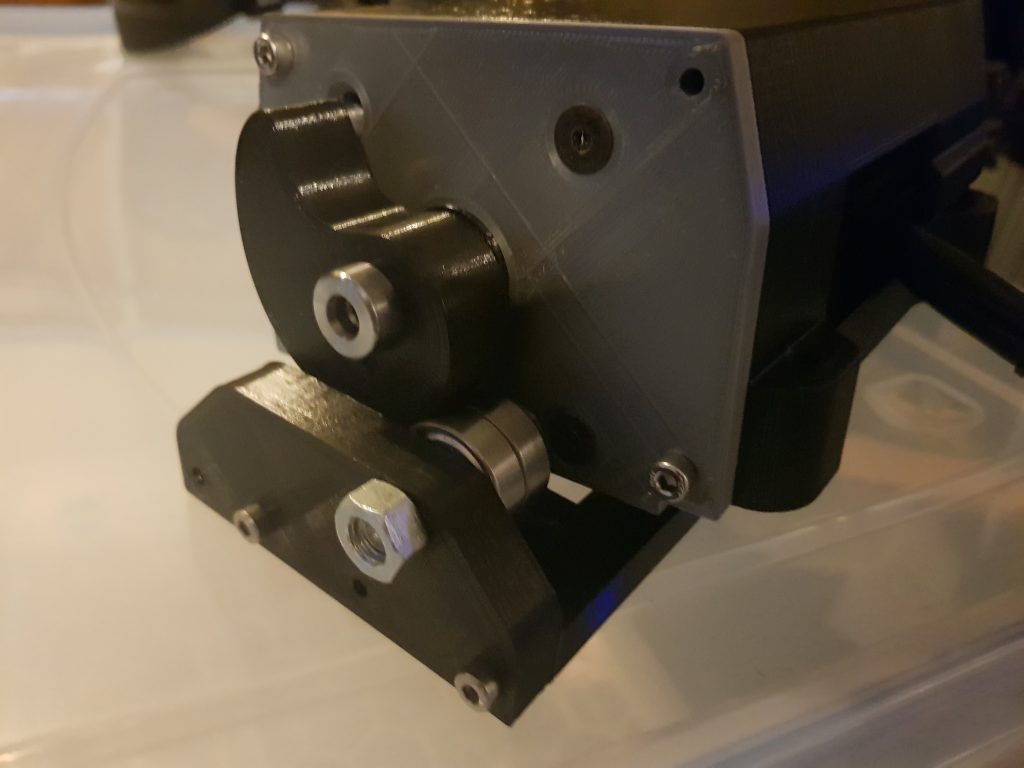
The other part of the design was the housing; getting my Fusion360 groove on I modelled a housing that would envelop the servos. #protip – this is *not* what you want when you realise how much power is actually required, these suckers get warm.
I now was at the point that it was mechanically working. That in retrospect has been about 4% of the battle. The other 96% (and I’m still going) is getting things not to explode into bits of plastic, bend, or slip.
Next up was testing/figuring out servo settings. The RPM setting was most enlightening indeed. This video below shows some various different speeds and what they meant for the motor pods.
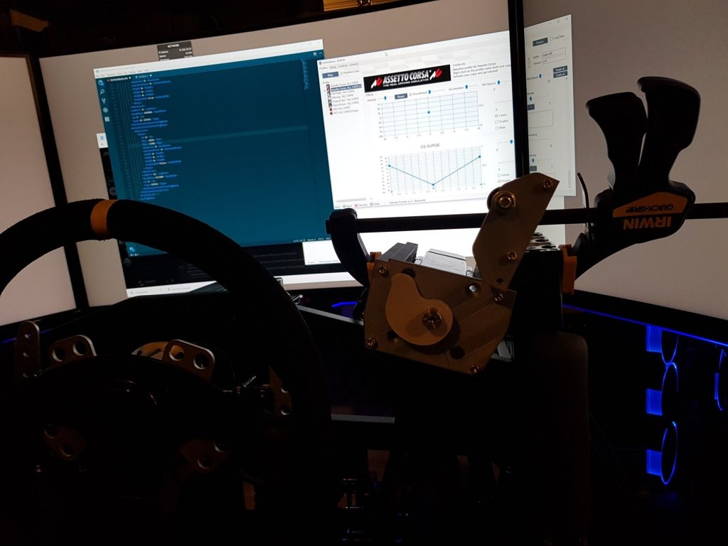
I mocked up a box, and put it in the rig. Very gingerly fired it up and tested it sitting in the seat. After seeing how fast those cams could move I was more than a little nervous trying it out.
To say I felt a little like Ham was fair

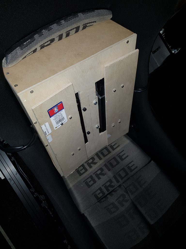
Without having broken ribs, at this point I was getting quite excited and figured out how to mount it in the seat. This was my first foray into outsourced laser cutting.
Once I got it mounted then I discovered my first problem.
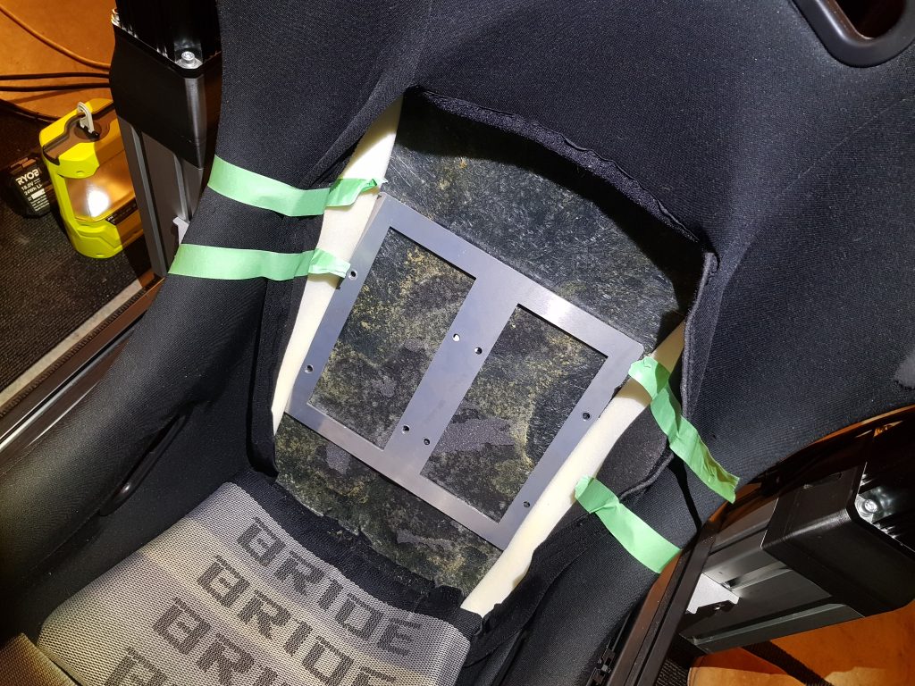
You need staggering amounts of torque to move humans. Which is not surprising when you think about how much force you’re exerting when hitting the brake pedal. Dinky little servos ain’t going to cut it here.
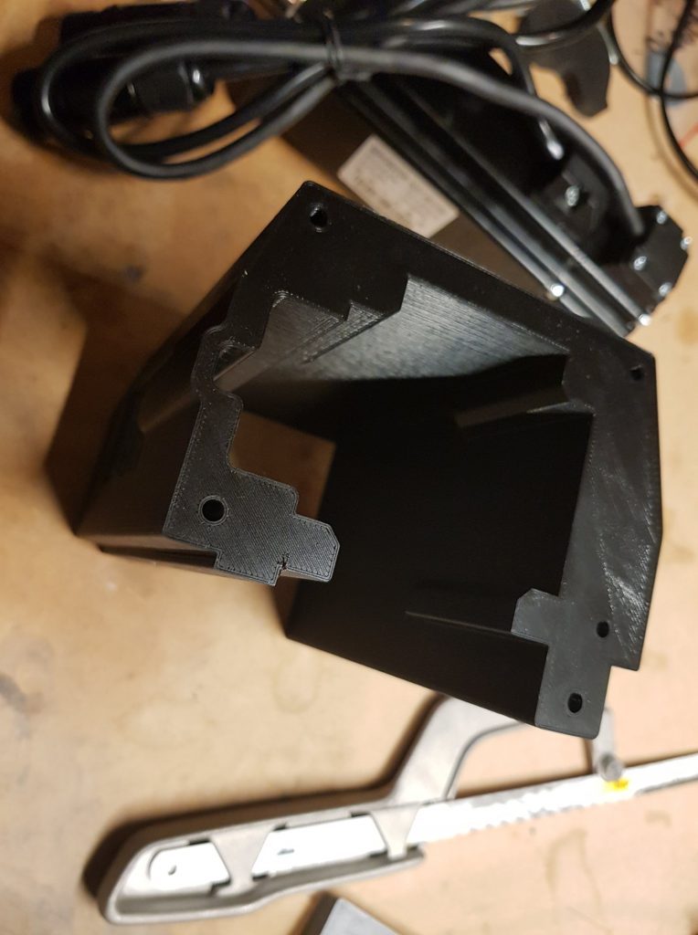
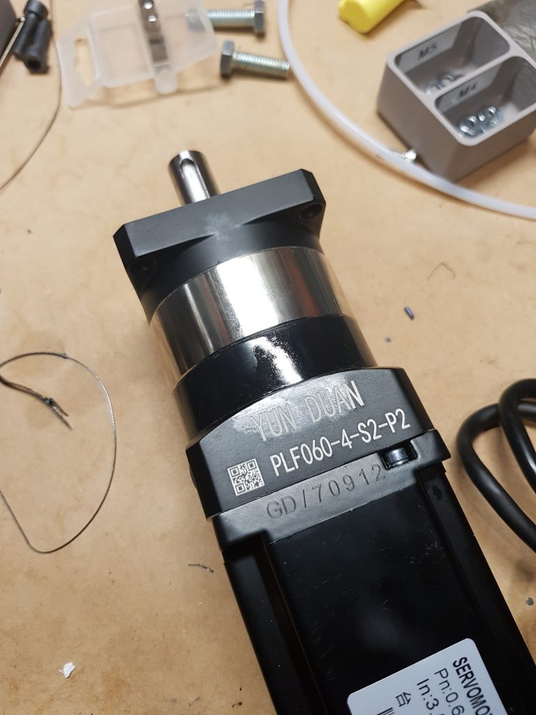
Next step; get some gearboxes. I went with a “suck it and see” approach and got some 4:1 units. No maths or science behind it just thought it might work. Another period of waiting from Aliexpress and I then Mr CourierPost dropped off my gearboxes.
And then I started breaking things


After mounting into the seat and starting to play with it, I started breaking things very quickly, cams, hinges, hinges, cams, cams hinges. The biggest issues were getting the cams to not have the key rotate inside them, and the hinge to withstand the load.
Carbon Fibre to the rescue, maybe.
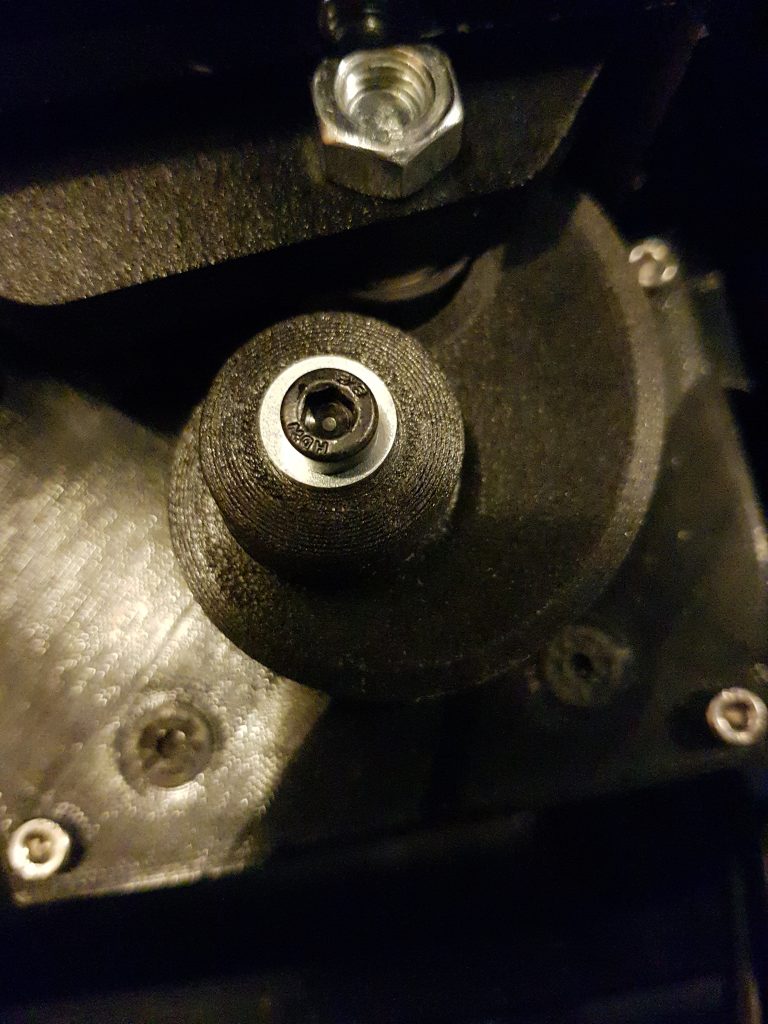
I discovered fancy Carbon NylonX filament thinking this might be my saviour.. it required a drybox, and a hardened nozzle to print with, along with brims to prevent warming.


After a bit of futzing around with settings I got my first NylonX prints out and they were GORGEOUS
I printed off my new parts, all excited, and, well you guessed it…

After a bit of work and a good idea from @C64, I modified the cam housing and this designed ended up holding up
Before the last gory details a few videos
On the home stretch?
I was getting excited, and more bolder in testing. There were a few nights there I was getting out of the rig with my lower back haven’t felt like an ass kicking by a thai masseuse. I kept plowing on with testing and design.
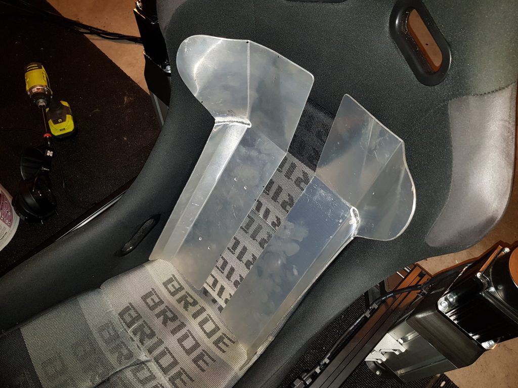
Time for the real test
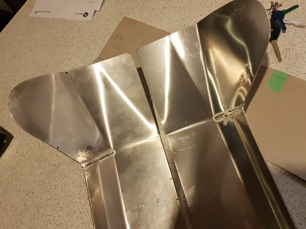
Now I needed to go to full height back flaps. A good friend with amazing skills built a set of flaps contoured to the seat – handforming, cutting and ali welding all in one !
This increased the load exponentially.. basically the hinge failed, within seconds. Not really a surprise but still disappointing. After 4-5 months of work on and off I huffed, and I puffed, and I walked out the garage dejected.
Onto Prototype #3…