Any of the works related to “@steely’s G-Seat” is Copyright 2020, Rowan Hick released under the Creative commons license Attribution-ShareAlike 4.0 International (CC BY-SA 4.0) . Read here for more details of what you can and can’t do, along with my intent.
Note will continually update this post until I’ve reached the point the powerpack is holding together; uphsoltery/finishing will be the next one.
Big shout out to: Bruce, Saxxon66, J.R, Buri, Flag, Volk etc and the rest of the Simfeedback discord – no way I’d be at this point without their input and help.
Now after a lull with work/life getting busy I set aside some time to put my SimRig back together and get on with making my G-Seat.
Rethinking everything and realising how cheap CNC machining/bending was – I had a good sold about the motor mounts. 3d prints weren’t going to work and I was struggling with the cams. With a little inspiration from @Buri’s super industrial approach, I thought maybe lets move to a pushrod approach vs cams. A few months back I’d gotten some belt and pulley components of AliExpress to try out so I expanded on the theory.
@Buris’ design is super industrial, looks awesome, however was very depending on a solid mounting surface (a Kirkey seat). On the other hand I had a cheapo fiberglass seat so I updated my design thinking to go “how much can I mount off one bracket” I wanted to isolate all the loads into one structural member that could be retrofitted to the back of a seat.
The trickiest part of the whole process was measuring the back of the seat; my mental image had a U shaped bracket that would slide onto the back of the seat, bolted in from the sides and the back. To measure it up I used Project Binky’s trademarked “Cardboard Aided Design” approach to get the basics fleshed out
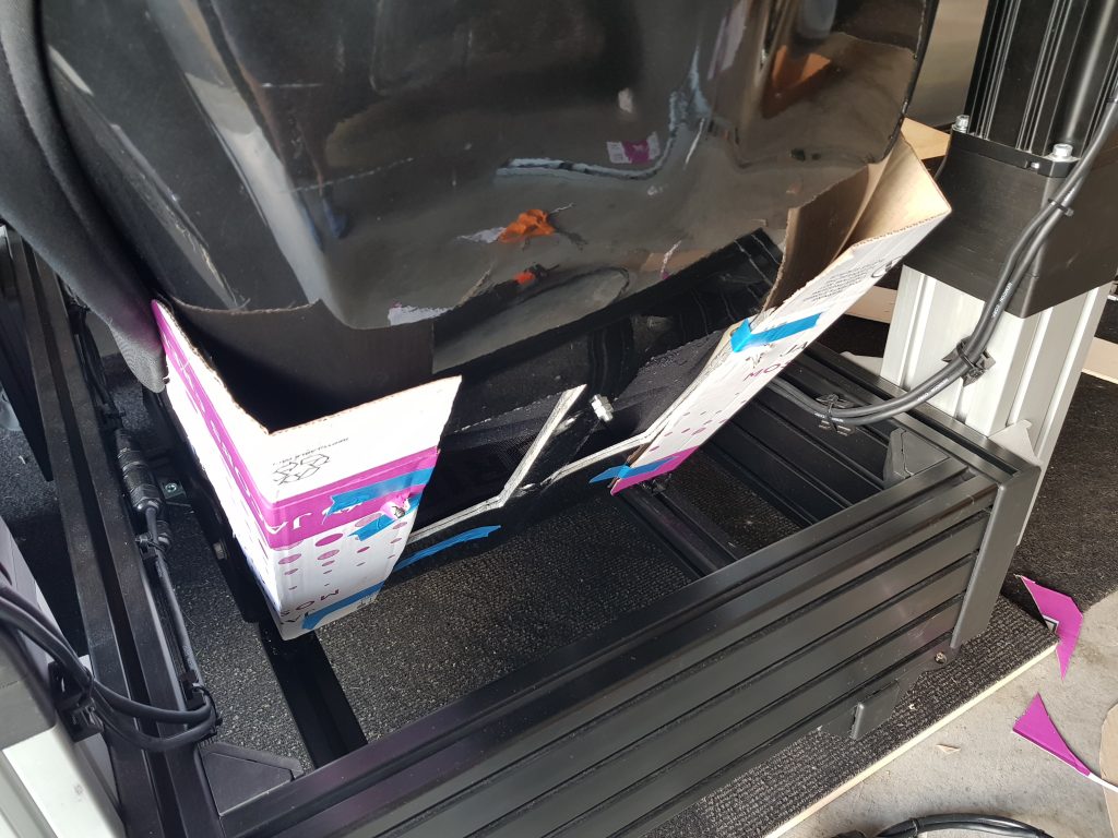
Compared to the 3d printing design this was 10x easier. All of about 4-5 hours I had a design ready to go – using Fusion360’s sheet metal function it was a doddle after an hour or so of figuring out the process between rules, flanges, bends and sketches.
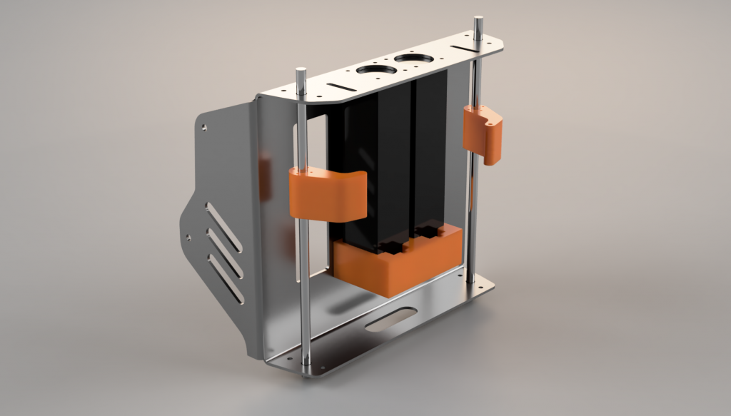
It took a few iterations to a design I was happy with, going from my initial concept top left, iterating right through to complete design.


Getting my first bracket made
After designing the panel I “flattened” it to a pattern in Fusion 360 and sent off the corresponding DXF file to some local legends.
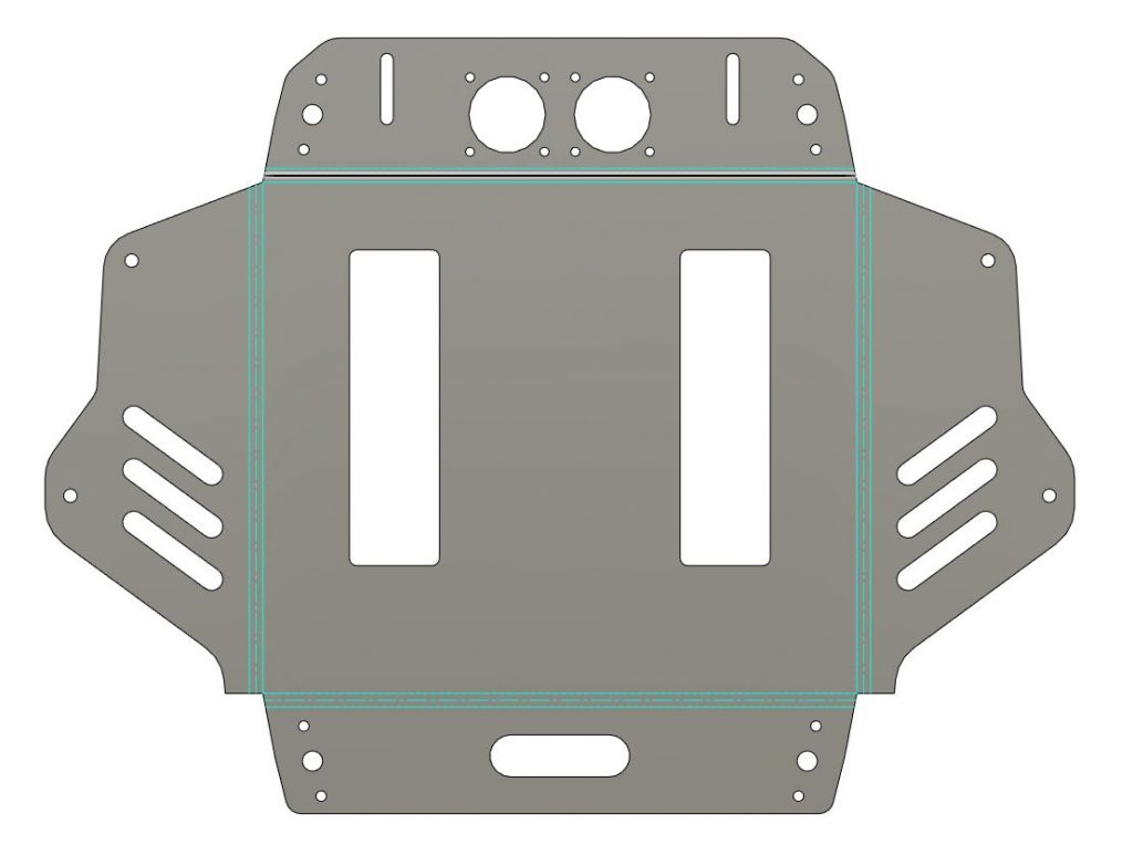
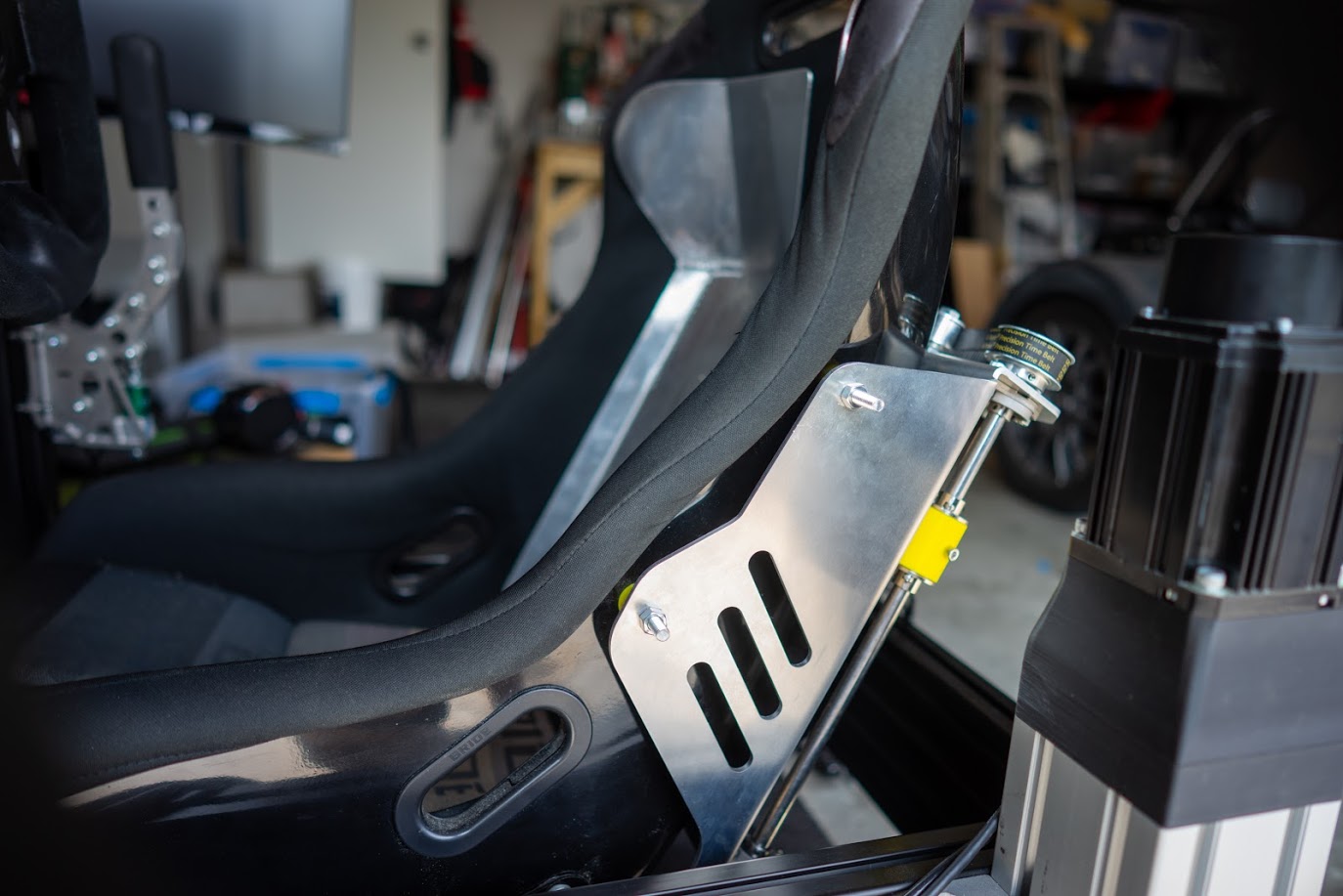
My cutting guys laser cut it and CNC brake folded it – which meant what I designed, is what I got. A week later I picked it and I was pretty damn stoked- when picking it up I got the “so what’s this for then?” question. I don’t think he really believed me…
The corresponding bracket looked great and more importantly everything fit perfectly which was a very good sign – even bends and k-factor/bend radii all lined up with what I’d designed.
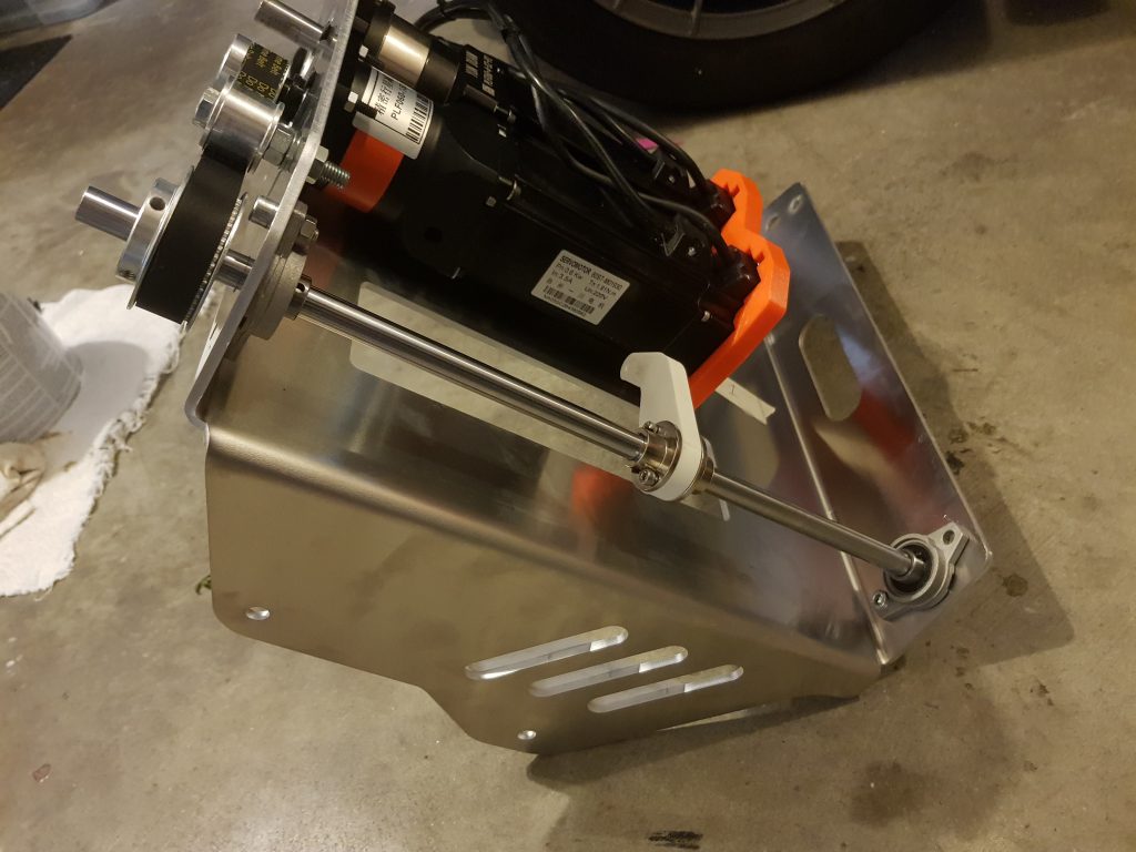
A little while later I’d printed up some arms, did a better job of mounting things, and got a mockup running on the back of the seat. I wanted to make sure there was no binding and needed to adjust the settings to make sure I had the appropriate range of movement.

SimFeedback/Controller Setup
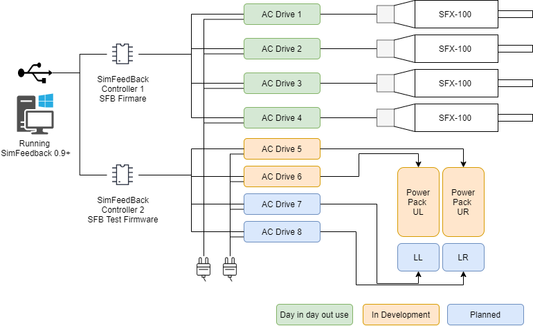
Well, we’re getting some serious juice into the rig ! Here’s a diagram of how the setup looks from a Software/Wiring side. Thanks to the Simfeedback multi-controller feature we can now run as many Arduino’s as our wallets and power outlets can handle (I don’t think the limiting factor is your computer!). Some of the earlier vids were from pre-release versions of SimFeedback, I’d been playing with this since about May or so last year.
Note: I leave the two controllers plugged in permanently and just plug in drives 5 & 6 when I’m testing. So some tests all 6 drives running, others only the 2 G-Seat drives.
First run
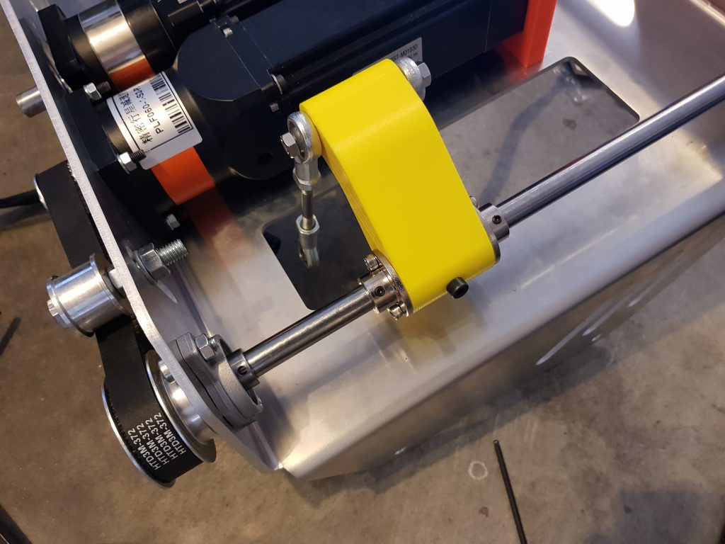
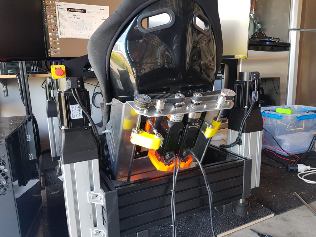
Getting excited I was nearing the first run. At this point I *hadn’t* mounted the seat flaps onto the pushrods, I just wanted to see what range of movement there was and get a good video for the YouTubes to convey what a G-Seat can actually do as it’s hard to see a feeling – but it’s easy to see pushrod arms moving.
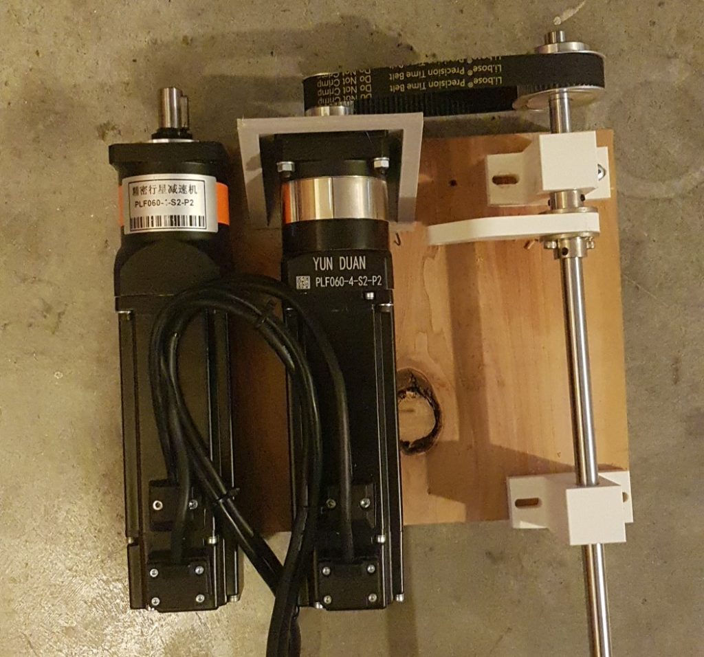
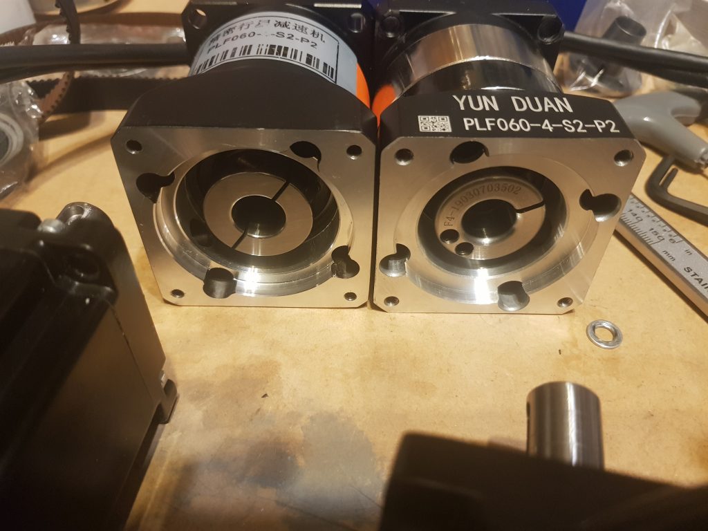
The basic principle is the motor; reduced speed through the gearbox, which reduced speed again through the belt drive (approx 8:1 total reduction); the final pulley moves a shaft, which pushes the lever, which in turn pushes the panels inside the seat.
If you are a sim rig aficionado and not getting excited at the above video, check your pulse. That’s *actually* conveying what the car is doing g-force wise, not the actual g-forces of course, but the g-force cues. Even just the first few seconds of the lateral side to side swing of spinning the tires coming out of the pits then letting the bite and grip. ACC has some amazing physics modelling and you really do feel it through the seat.
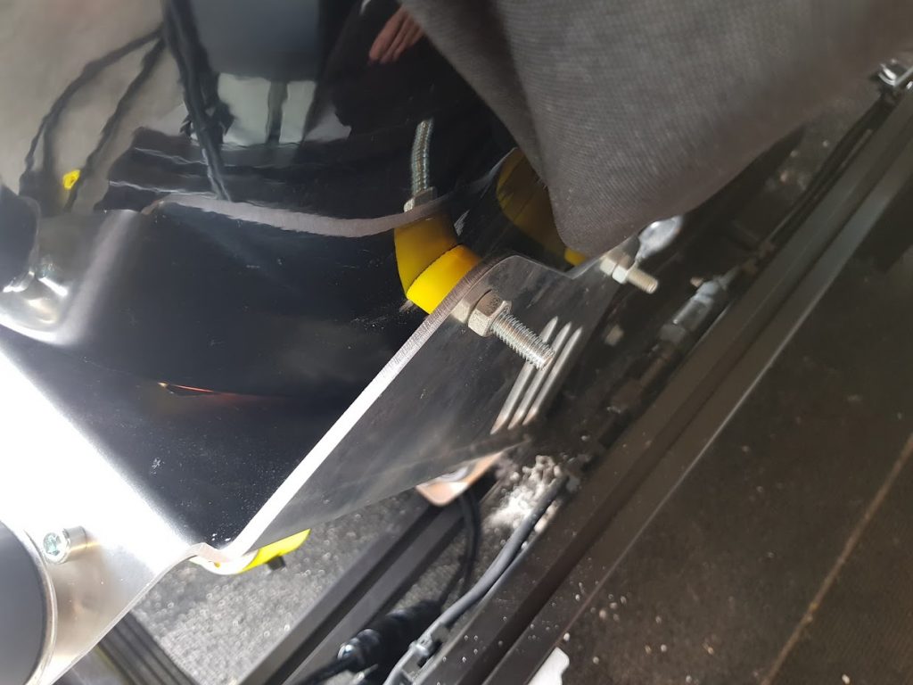
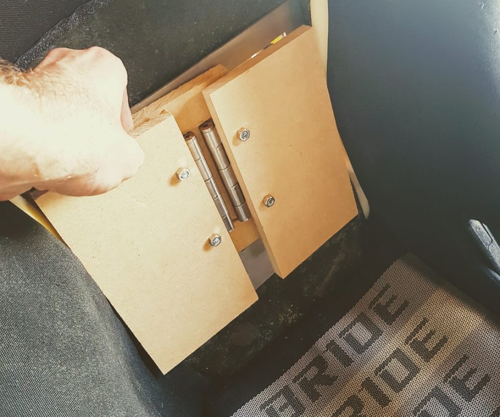
Speaking of feeling it through the seat, I needed to actually connect the flaps up somehow. So first off I built some mockup MDF flaps with standard door butt hinges, like so.
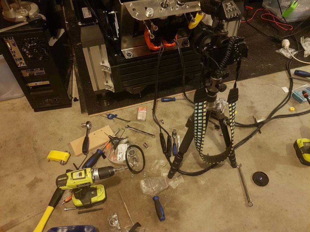
And then for the umpteenth time pulled everything apart again, to get some bolts in, to bolt it all back up again. This is the state my garage floor keeps looking like:
We now had a working seat that I could start testing with. Let the fails begin !
The fails – how long will the 3d printed arms hold up?
#1 Grub screws/hardened steel rod
I’d used hardened rod for use in things like 3d printers. Don’t do it – grub screws have no interest in holding it. Drills have no interest in drilling it. Files, forget it.
Solution: Upgrade to Mild Steel Rod (knowing it’s going to rust later…) Note I ordered from RS components 1m x 12mm, I ended up getting a tube of 6 x 1m, must be a website error, but very handy in retrospect….
#2 Grub Screws
The standard grub screws in the pulleys kept slipping.
Solution: Thanks @Buri and @Bruce Get M5x10mm grub screws and drill locating holes into the rod; use keyway to locate grub screw on gearbox pinion.


#3 Gearbox slipping
Next issue – it looked like the input shaft of the gearbox was slipping on the motor output shafts. In retrospect I’m not entirely sure this was actually occuring. However…
Solution: Have a good friend by the name of @Bruce to whip up a thin keyway inspired by @Buri.
#4 Belts slipping
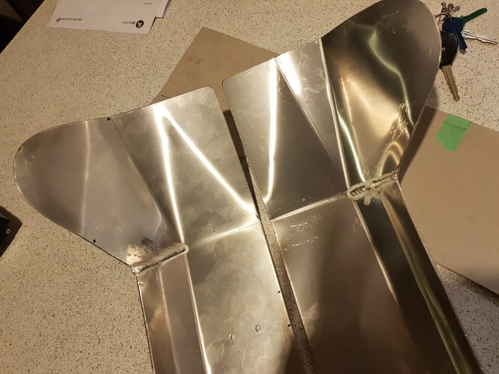
Being bold I put in the full alloy panels into the seat.
In almost a surprise to no one; I found out the belts were actually slipping. Installing the gearboxes with their new keyed inputs I was most disappointed to find out that there was still a “snapping” noise. I’d marked all the shaft positions, etc and couldn’t for the life of me realise what was going on, until it dawned on me.
Solution attempt 1: Not successful – I added another idler pulley on the top side of the belt, the belt held up longer, but still skipped. It has some monster tension through it so not at all viable.
Solution attempt 2: In progress- I’m now waiting for some gruntier 25mm wide belts, 5mm pitch from Aliexpress. With an increase in ratio, belt width, belt pitch, and pulley sizes hopefully this get’s resolved.
Stay tuned.


That’s brilliant. So many questions, but one that pops up is; (a) how did you calculate the total required reduction, and (b) decide how to split that reduction across the gearbox / pulley combination?
Hey Roger – on prototype #2 I kept overloading the servo so added a 4:1 gearbox by pure guess work. For #2 I already had the gearbox but figured it needed some degree of reduction as I was reducing the # of degrees the arm was moving.
Thanks for the reply Rowan. Do you have a choice of adjusting the #degrees of arm movement physically via gearbox/pulley, *or* within Simfeedback? Is the balance between those two things all part of the black art, trading off torque versus distance etc?
And is this all being controlled by an Arduino setup, or one of Thanos’ devices, or…?
Hey Roger; you’ve got a number of different places to do it. I use SimFeedback as (1) I’m the core team for SFX (of course) but more importantly (2) you have a lot more control over *how* the arm moves (ie linear versus a curve). and (3) ultimately I’m going to have at least 8 motors on this bad boy 😉 I’ll put up a post about this at a later date.
For the actual degrees of movement this is controlled by the servo drives themselves, you can just set the pulse multiplier lower as required. Then in Simfeedback the intensity control determines how much you use of that.
Cheers. My SFX-100 parts are on order, so thanks for your part in developing it! If that goes well, then I’m just optimistically thinking ahead towards RTL and/or surge and/or this.
Ah, I’ve just read your Prototype #2 page, revealing the use of the “suck it and see” approach”!! Thanks Rowan, very good writeups.
[…] this is a factor in my decision making process.. if I got my G-Seat to a good enough space that it was releasable open source, would I do it? I probably would.. but if […]