Introduction
It was going to happen sooner or later, a motion platform for the sim rig. After much research and flirting with the prospect of getting a motion platform (I’d been projecting it to be year(s) away, if at all) I stumbled across this cool project https://github.com/SimFeedback/SimFeedback-AC-Servo.
Doing the sums my ears pricked up, or more to the point I got my google on to research it. A handful of videos later with some very interesting quotes got the ball rolling – some people were comparing it to a middle of the road between a SCN-6 based unit to a top end DBox unit.
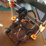
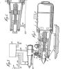
What is it? Essentially a DIY linear actuator design, with software (SimFeedback) and an Arduino firmware package to drive 4 actuators in a platform mover design. The actuators are a combination of a Servo Drive, mounted to Ball Screws with a bunch of 3D Printed and off the shelf parts. See here for the full details https://github.com/SimFeedback/SimFeedback-AC-Servo
I’ll just give the abbreviated version :
- 4 Servo Drives; these come with control units and power suppliers
- Arduino wired up on a breadboard to 4x (old school!) DB25 connectors that hook up to the control units
- 100mm box section extrusions that form the actuator
- Motor on top
- 3d Printed pieces to interface motor to Extrusions
- Motor then has a coupler that joins to a ball screw
- Ball screw has a 3d printed slider that slides inside extrusion
- Other end of the slider is the ‘foot’ a stainless rod
- On the bottom of the extrusion a 3d printed cap that includes a linear bearing.
Why would you build one? Price up a DBox and you’ll see why. $30-$50’000 NZD is a heck of a lot of money. Even a Seat Mover design with only 2 actuators off the shelf would be up near $6’000+ NZD. This comes in significantly under that.
The DIY supply chain
This project won’t be for everyone. There is lots of research, finding parts, ordering bits and pieces from around the world. I had no less than 12 places to get stuff from, and I’ve not even started assembling the actuators.
You could tell looking at Amazon that a bunch of things were sold out as there’s quite a few people building these platforms. If you were in EU this would be much easier and you could use the recommended suppliers for more things. The items in bold are the really important ones that you (I think) need to stick with the original suppliers, there others you could take more of a gamble with.
- Servo Drives, Ball Screws, Fixed Bearings – AliExpress. Special mention to the David at the Master Jiang 3SMT store (https://www.aliexpress.com/store/3223052) for the servo motors, super to deal with.
- Extrusions, Helicoils, T slot nuts – Haec
- Linear Bearings, Couplers – Dold
- Stainless Rods – SmallTec
- Arduino, DB connectors, wires, breadboard, estop, anti vibration feet – Amazon
- 3d Printer and PLA – Prusa
The following needed to look through NZ suppliers to get :
- DB25 cables – RS components
- O-Rings – Blackwoods (New Zealand)
- Low profile cap screws – Steelmasters (New Zealand)
- Cap screws and washers – I couldn’t find 85mm M6’s, however 90mm M6’s seem to be fine. Fast Trade (New Zealand)
- Power cables for Servos – Mitre10
- Terminals – Repco
Recommendation: Order everything in one go.. it will seriously take a few hours, but better that than waiting for final pieces of the puzzle to turn up. I started mid October and now December bits are still arriving 🙂
Update 21st Jan 2019 :
1) there’s a really good shopping list here by HugoB with some US specific items for any North American readers, along with the alternative supplier “Emily” who’s packaging up a bunch of the mechanical items for good prices https://www.racedepartment.com/threads/the-simfeedback-ac-diy-motion-simulator-thread.159524/page-98#post-2899157
2) Please have patience with Kinetek, ordering custom cut extrusion profiles from an engineering company is a bit different than off the shelf consumer goods. You’ll need to allow a good few days for responses and weeks for fulfillment. Our orders are very likely out of the norm for a company like Kinetik so patience is a virtue here.
The 3d Printing Rabbit Hole
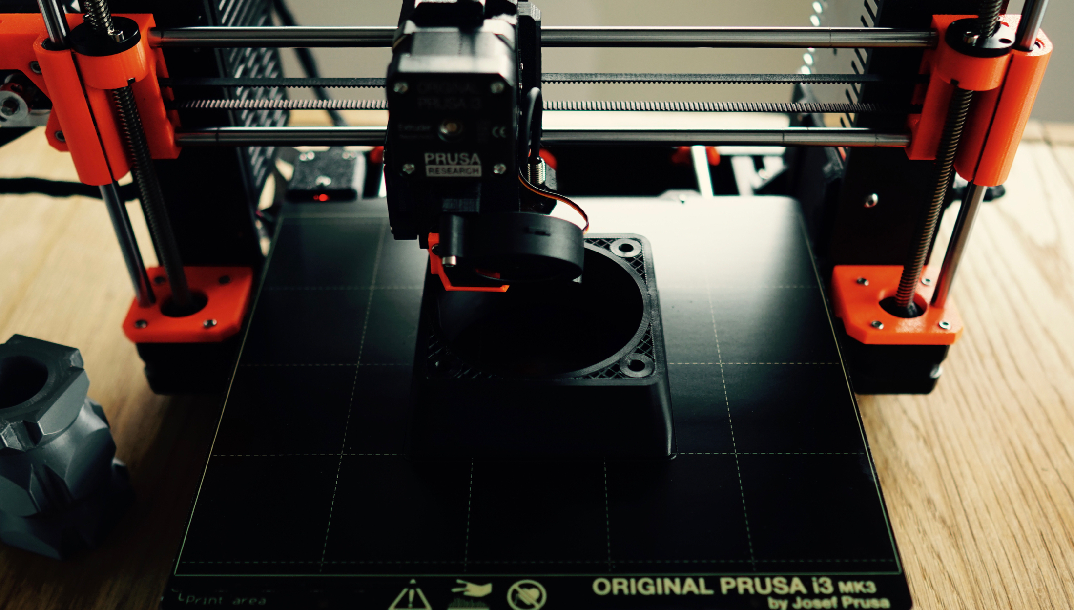
The last time I tried to get some parts 3d printed here by services it was pretty expensive and results quite variable. Doing the mental sums it probably wasn’t cost efficient to outsource the printing, so using a bit of man maths I decided to take the plunge and get a Prusa i3 MK3. Once you get past the branding (no mistaking what it is) you’ll realise it’s a pretty serious bit of kit for comparatively speaking not a lot of money.
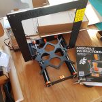
The printer in itself was it’s own mini project – I bought the kit version and waited patiently for it to arrive. It only took a few days shipping and DHL were very fast at customs clearance. I wholeheartedly recommend the kit process, was a lot of fun to build and understand how it works.
Printing off the test pieces I was staggered as to the quality. Definitely left the printed things I’d seen before in the dust. The layers went down to 50 microns. It took a good 4-5 hours of playing around until I managed to get the live Z adjustment right and layers right.
The other side benefit of the printer was my other half got interested in it. Seeing items turn from plastic filament on a roll into a solid component is very, very cool.
After a good week or so playing around with various prints I started on the rig parts proper.
Printing the components
Update 8 Jan: You’ll want to read this bit about printer calibration to avoid an issue I had with the sliders not *quite* dimensionally correct. https://www.racedepartment.com/threads/the-simfeedback-ac-diy-motion-simulator-thread.159524/page-20#post-2847744
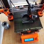
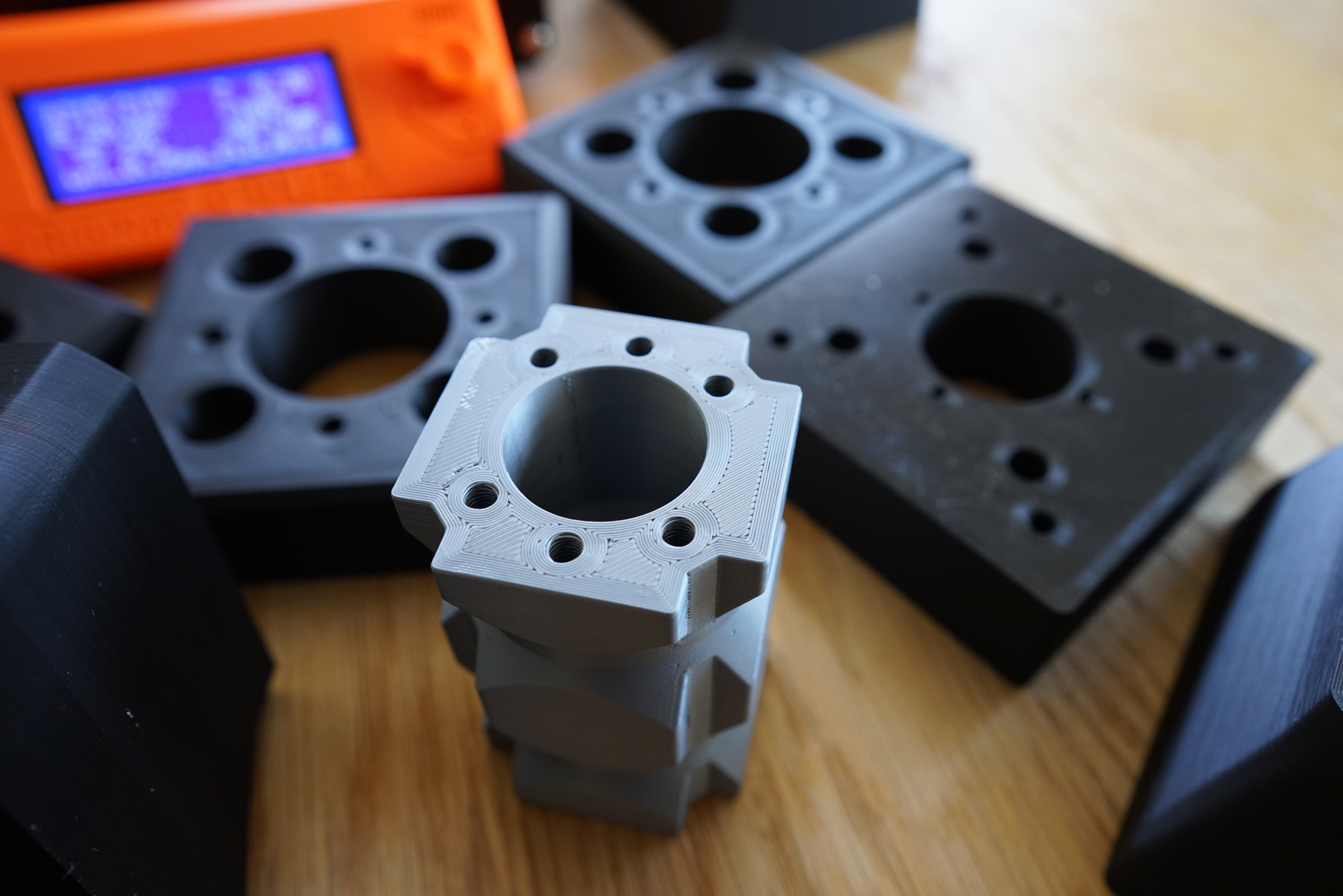
I started with the sliders using the supplied silver PLA filament while I waited for some black filament to turn up. This is the process :
- Get the .STL files from Github to your desktop
- Download and run Slic3r PE edition
- I created a custom profile for 0.25mm layers with these settings
- I used 20% profile as a starting point
- Print Settings Tab:
- Layers and Perimeters
- Layer height: 0.25mm
- Perimeters: 8 minimum
- Horizontal shells Top: 12 Bottom :12
- Infill
- Solid infill every: 20 layers
- Fill density: 20%
- Layers and Perimeters
- Then open up each .stl file and slice it
- Export .gcode
- Save onto SD Card and start printing
All up there’s 180+ hours worth of printing, so when the guide says 2 weeks, it’s real. I printed the sliders first, once the black PLA arrived, then got down to business :
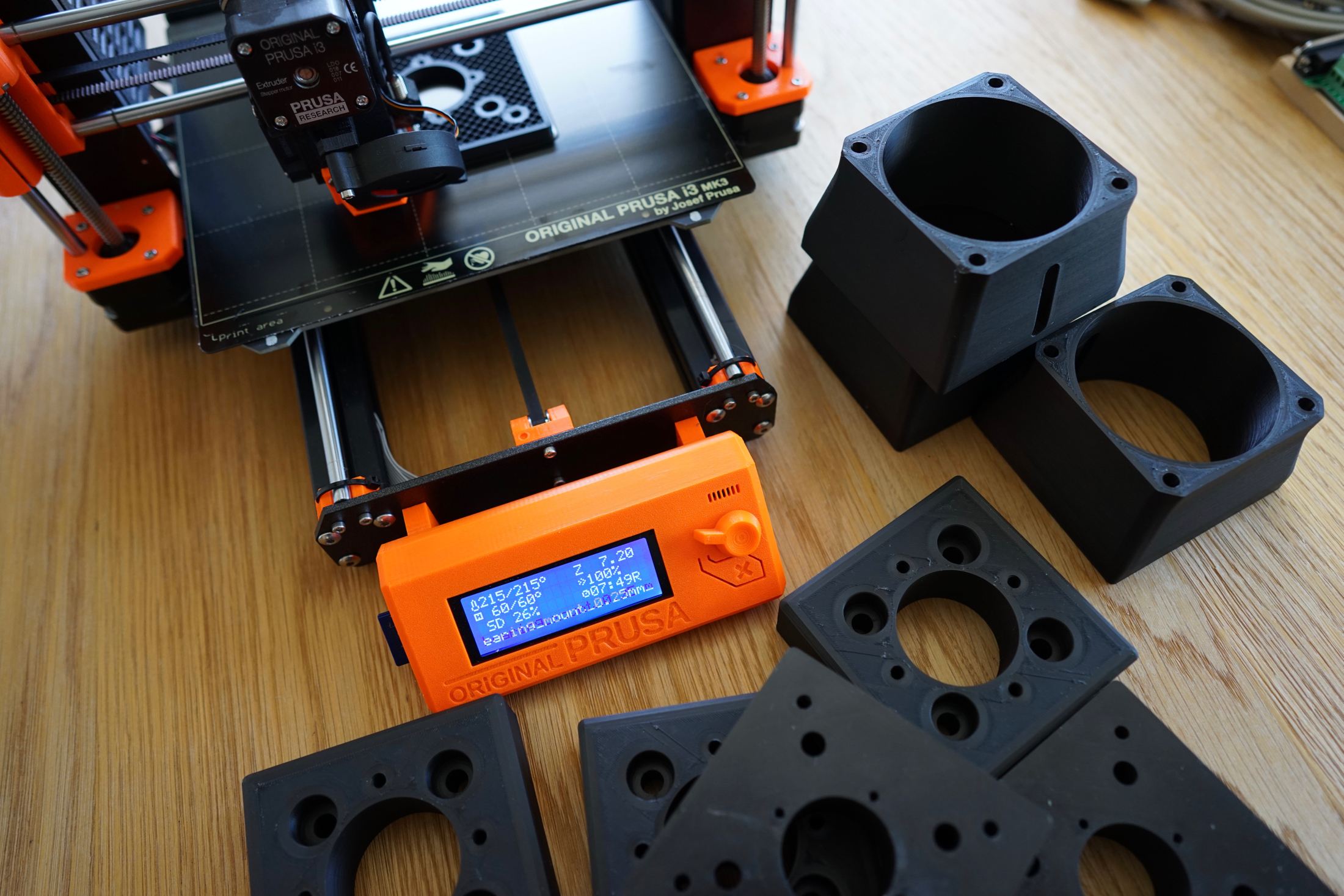
The results were quite good on all the visible surfaces, save for a little warping which didn’t make a difference once you started bolting up.
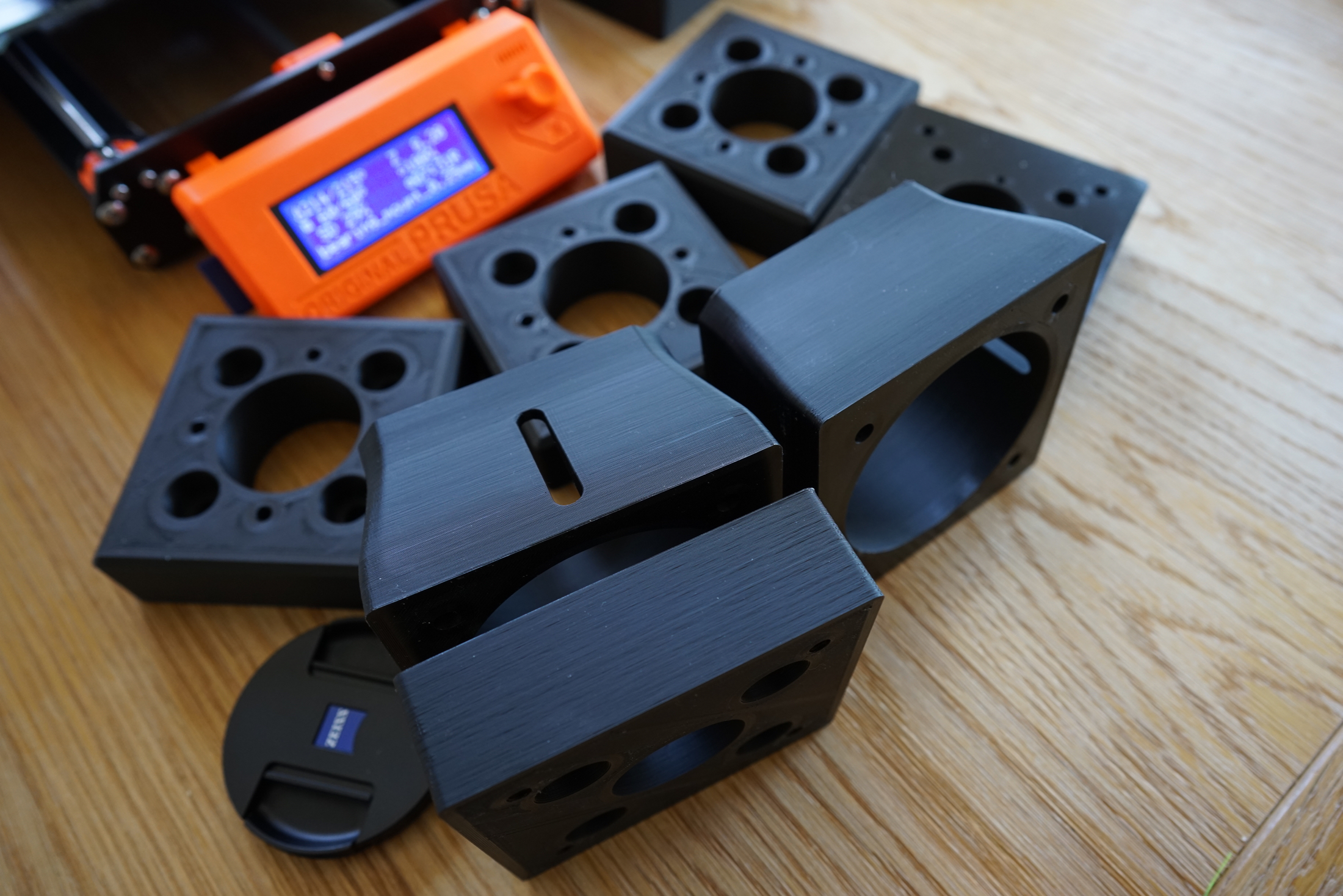
For some strange reason there was this weird artifacting on one side of the motor mount – given it was consistent and on one face only, I suspect it was a gcode issue – when importing it I think there was an error that was “self repaired” by the slicer. Other than a visual oddity not worried about it.
Recommendation: Don’t mess around with cheap filament, I ended up a test roll of some locally supplied stuff and found it to be a stringy mess, so just ordered a boat load (on sale!) from Prusa that turned out cheaper than anything here.
While the parts were printing the first motor had arrived and I started test assembling actuator #1. So with the first one done I’ll roll through assembly of actuator #2 with a couple of hints to make things a bit easier along the way.
Warning for those that don’t read instructions. I should have done the electronics first before bolting the motor up, okay as it was only the 1 motor.. so I can test it all on the second motor.
Next post : Assembling the actuators..
Next Post: Electronics and testing

Hi Rowan,
An incredible website, I’m loving cruising around in it.
Thanks so much for your care and attention compiling it.
Thanks Matt ! Much appreciated.
Hi,
What does the artefacting look like on your motor mounts? I just printed my 1st mount and there’s a weird artefact on one side that looks like diagonal lines, a few random dots and what actually looks like a series of numbers. Very odd.
Thanks,
Ian.
Hello Rowan. I am in Australia. Could I talk to you on SKYPE re sourcing of parts?
Thanks,
Peter
Hey mate I’m really busy at the mo. On Facebook lookup SFX 100 group and you’ll find a couple of recent posts where a bunch of Aussies are discussing sourcing. They’re going to know far more than I on this. Cheers !
OK. Thanks Rowan