I charged ahead with building the first actuator before wiring up the electronics and testing the motor. I should have done this first, so you get the benefit of my hindsight.
1. Get your AC Servo drive powered up and configured
DISCLAIMER you are messing around with mains voltages. Make sure you know what you are doing, if in doubt consult an electrician. The servo drive does not come with a standard AC/IEC plug – you need to wire this into the unit yourself.
The AC Servo drive has two types of input power it can accept, single phase and three phase. NZ is single phase and as such (on my one, and again, you need to do your own research) L1 was phase, L2 neutral and earth the terminal on the case. L3 wasn’t connected to anything.
Plug the servo into the controller, turn on the mains (be very careful) and make sure it powers up properly. Assuming it does then run the test according to the guide.
Now, program the Servo Controller. It’s pretty simple:
- Press Mod until you’re in programming mode
- Then press up/down to find the setting you need to change, press set, it will change to it’s value
- Then press up/down to the right value
- Then press set, it will flash to indicate it’s programmed
- Then press set again to go back up to the original program setting [note this won’t be necessary if you haven’t changed its value]
- On to the next number, rinse and repeat 3-5
2. Wire the USB controller and flash it’s firmware
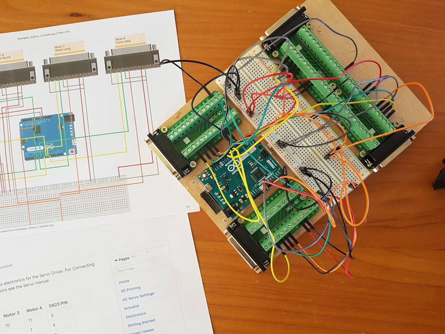
Like a few of the units on Github I elected to do the “lets just throw this together on some wood and worry about it later” approach to building the controller. When I have some time I’ll design and print a proper enclosure for it.
A bit of 6mm MDF some woodscrews, double sided tape and 15mins later voila
 I started connecting the wires and then undid it all to find a good approach :
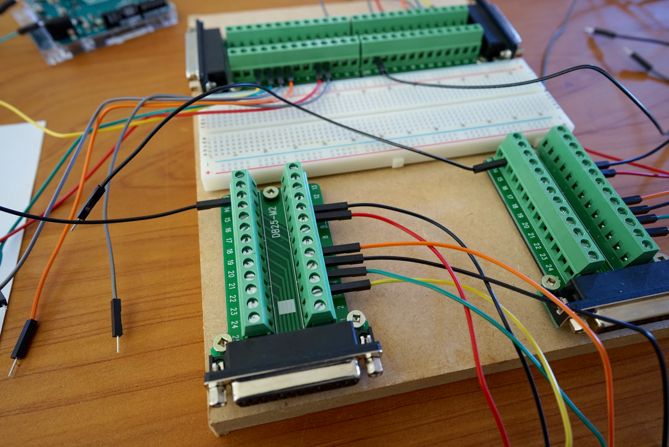
- Start with the first DB25 connector
- Wire it (follow the DB25 column in the table on the electrics page), with the wires loose
- Repeat for the other connectors, it will look like the above photo
- Then do the individual yellow and green wires to the arduino as they’re uniquely terminated on the Arduino
- Then do the orange wires
- Then finally the +ve and gnd common wires
- Check, recheck and recheck again
When it’s done, stand back and admire your artwork.
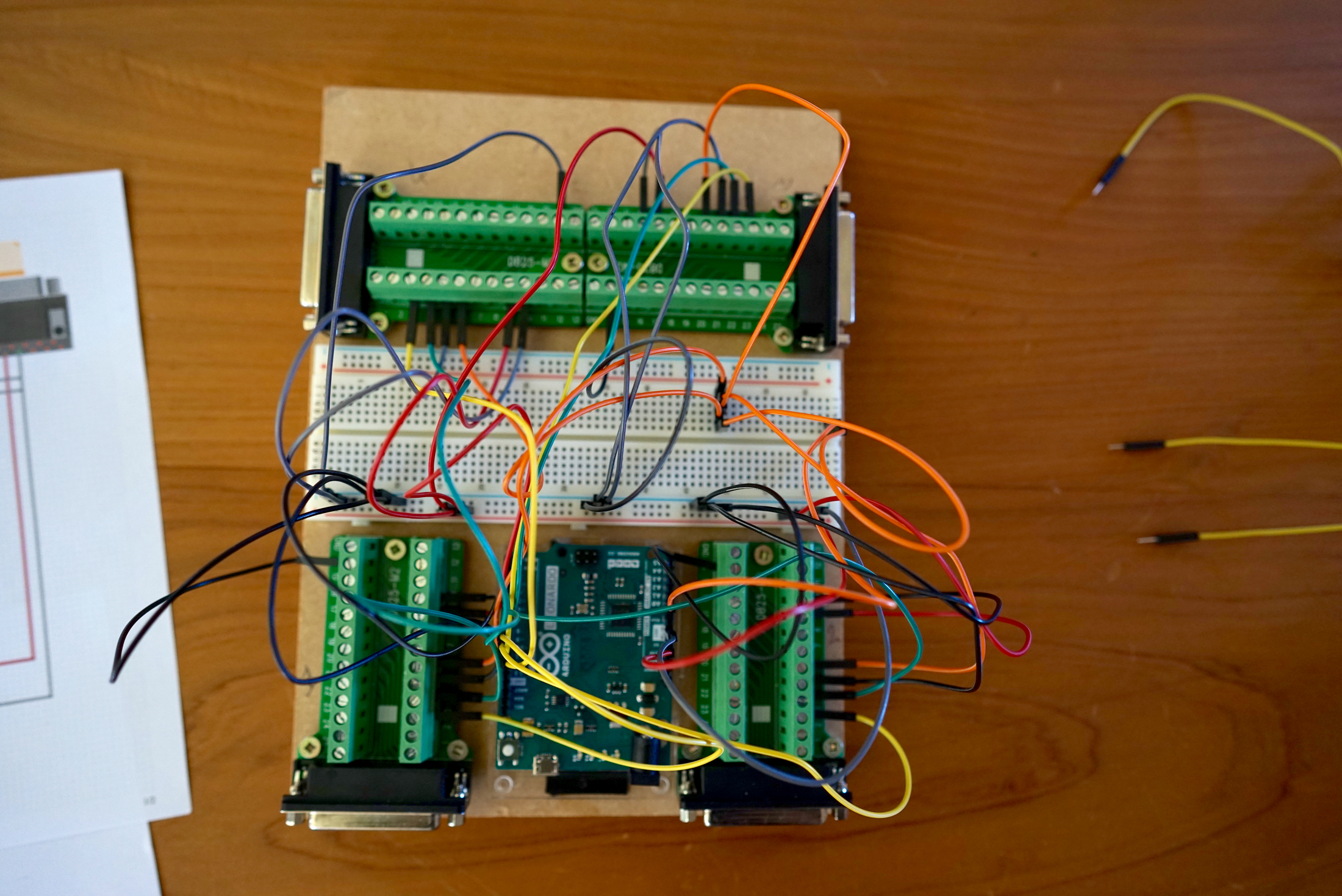 Now hook it up to your PC and flash the firmware. All going well you’ll have a controller board ready.
3. Testing time, gulp !
Okay, you’ve got the ingredients – a USB Controller, the AC Servo controller, so in theory if you’ve done it all correctly your servo will work.Now make sure your servo is not connected to the actuator, as if it goes wrong, it won’t be pretty (something will break no doubt).
- Plug USB Controller board with one DB25 connector into one of the AC Servo Controllers
- Power on the AC Servo controller
- Plug the Arduino in
- Load SimFeedback, ensuring your COM port is selected
- All going well pressing the start button in SimFeedback you’ll see…..
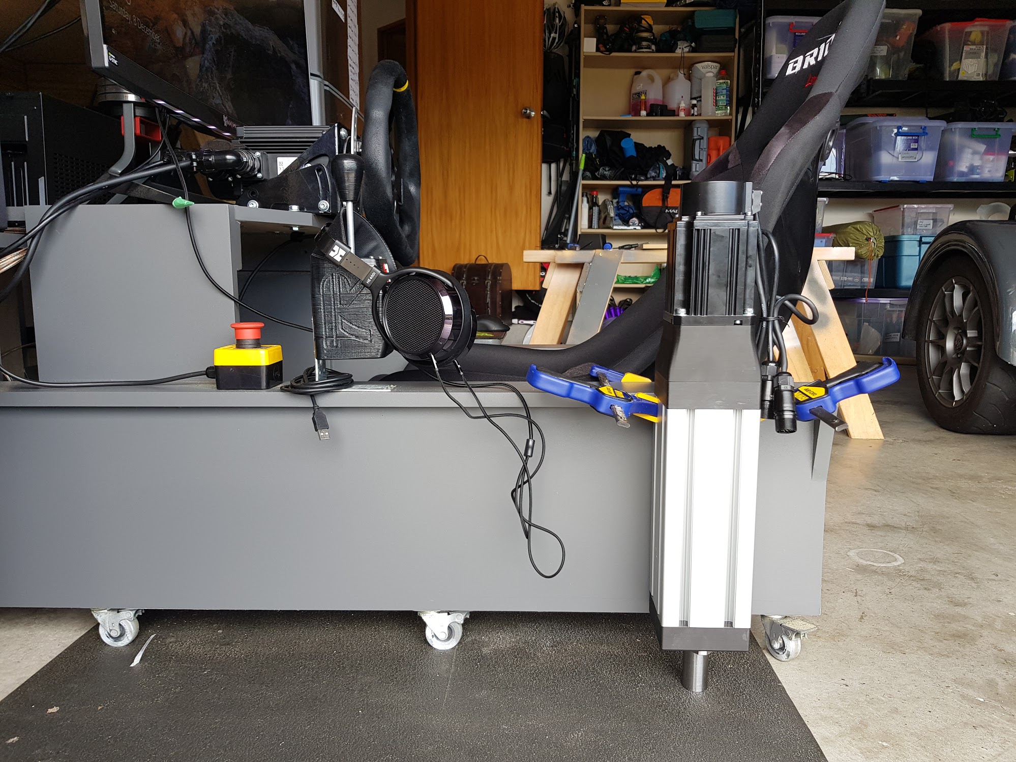
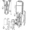
If it looks like the above, you’re off to the races. At this point, again I’d already raced ahead and built my first actuator naturally I’d put it next to the rig just to see what it was like for scale – here’s a photo just to give you an idea of what it would look like :
4. Telemetry time
Now, not one to wait patiently, I figured out SimFeedback and changed the RPM setting on the drive to 3000, just to see what it was capable of. I started the AC profile on ACC and stood back to bask in the glory of one very cool DIY project doing its thing.
Gotta say, I was pretty stoked it all worked first shot.
5. Thoughts for design on a proper enclosure
My Servo drives came with a spare DB25 terminal, with a bit of soldering work you could get rid of the bulky screw terminals, bread board and put it all in a nice neat enclosure. If I pull it off and do a good job I’ll share some STL files.
Next post
I’ll walk through the assembly process of an actuator with some tips along the way.


Awsome tutorial!
But i missing the firmware for the arduino leonardo have you the sketch?
I cant find it, even in the wiki
You install it as part of running SimFeedback… I can’t recall which tab (not infront of PC at the mo) basically you go into setup area -> select com port -> select & upload firmware -> done.
Do you know the printing costs? for all the parts?
No sorry – the raw PLA is 3 rolls worth, in NZ that was about $120NZD worth of PLA + Printer. From what I know of 3d printing services, you’re probably better off buying a printer.