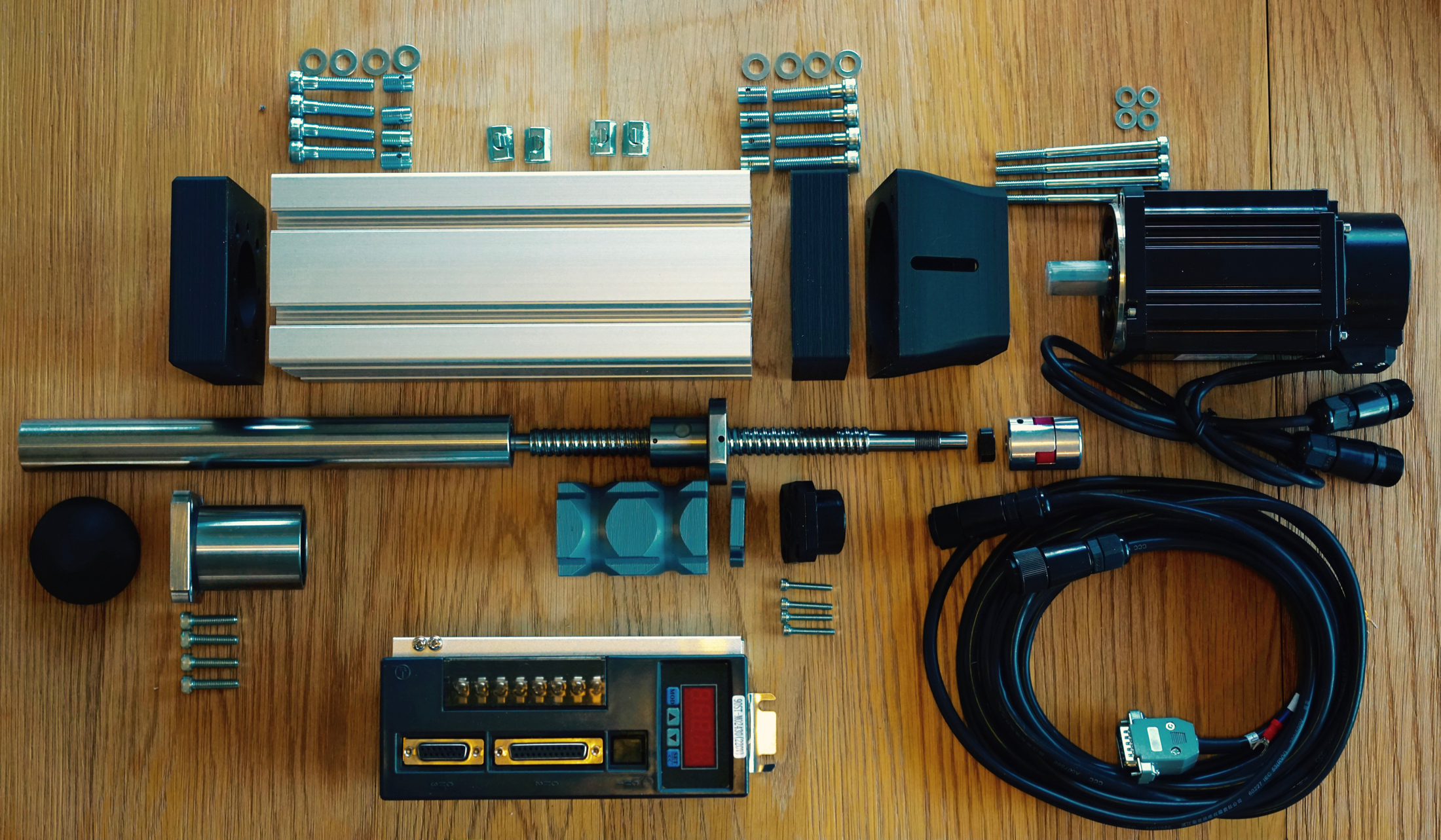
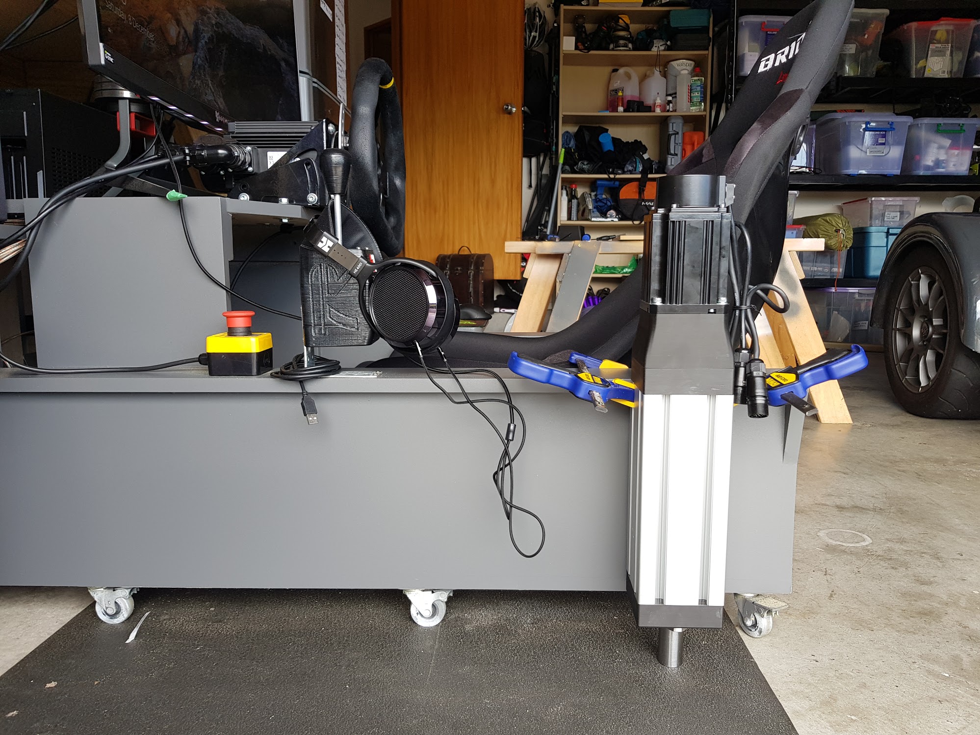
There’s a surprising amount of parts that go together to form the actuator, and it’s even more surprising exactly how much weight they can not only hold, but move.
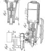
Above is almost all the bits (save for one O-Ring and 6 screws I forgot to photo) that goes into the actuator.
The instructions are very good https://github.com/SimFeedback/SimFeedback-AC-Servo/wiki/Actuator I’ll just put down a few tips here.
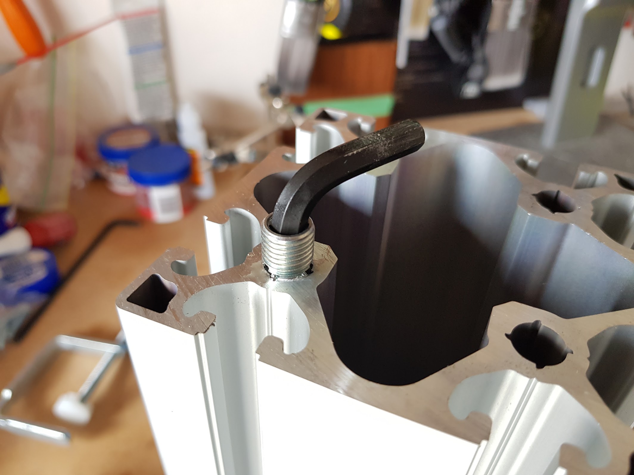
Tip 1: Having tapped a few threads in my life I wasn’t looking forward to the prospect of messing up the helicoils. Going through the tools in the garage, the thing that worked wonders was a 1/4″ Allen key that was super long – I could use it to get the helicoil lined up as it was starting the thread, keep it aligned up until I had to change to the short end to do the real work of cutting the thread.
Make sure you put oil on the helicoil’s threads to help make it easier.
Update 31st Jan – 2 other SFX builders have put videos online of the two different methods for inserting the Helicoils.
Option 1 – by hand
Option 2 – by machine
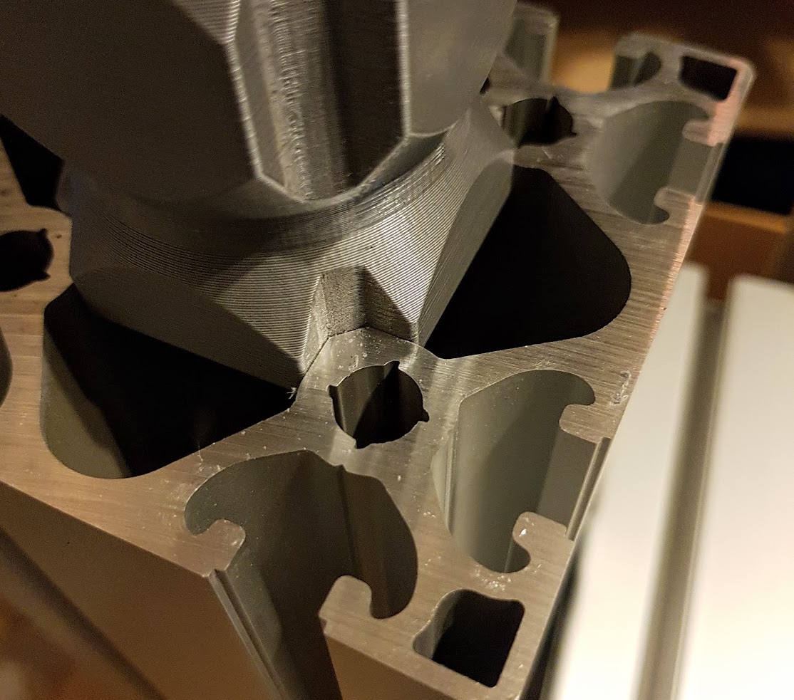
Tip 2: The sliders – on my particular print settings they were too tight to fit in the extrusions. I needed to run a dremel down each groove here. I think I must be a unicorn on that front, hadn’t read any other reports of this. YMMV.
Update 8 Jan: You’ll want to read this bit about printer calibration to avoid an issue I had with the sliders not *quite* dimensionally correct. https://www.racedepartment.com/threads/the-simfeedback-ac-diy-motion-simulator-thread.159524/page-20#post-2847744
Tip 3: Don’t wind the ball screw too far off when screwing the threads. That’s in the instructions also. Real b—-d of a thing to get it back together if you do make a mistake here.
Tip 4: When assembling fixed bearings into the blocks. Put some grease on the thread of the screws – at least for mine they were quite tight, and in fact I was worried I was going to snap one M4 on the little fixed bearing.
Tip 5: Don’t worry about any slight warping of the plastic pieces, I had some on mine and tightening up the bolts got rid of it.
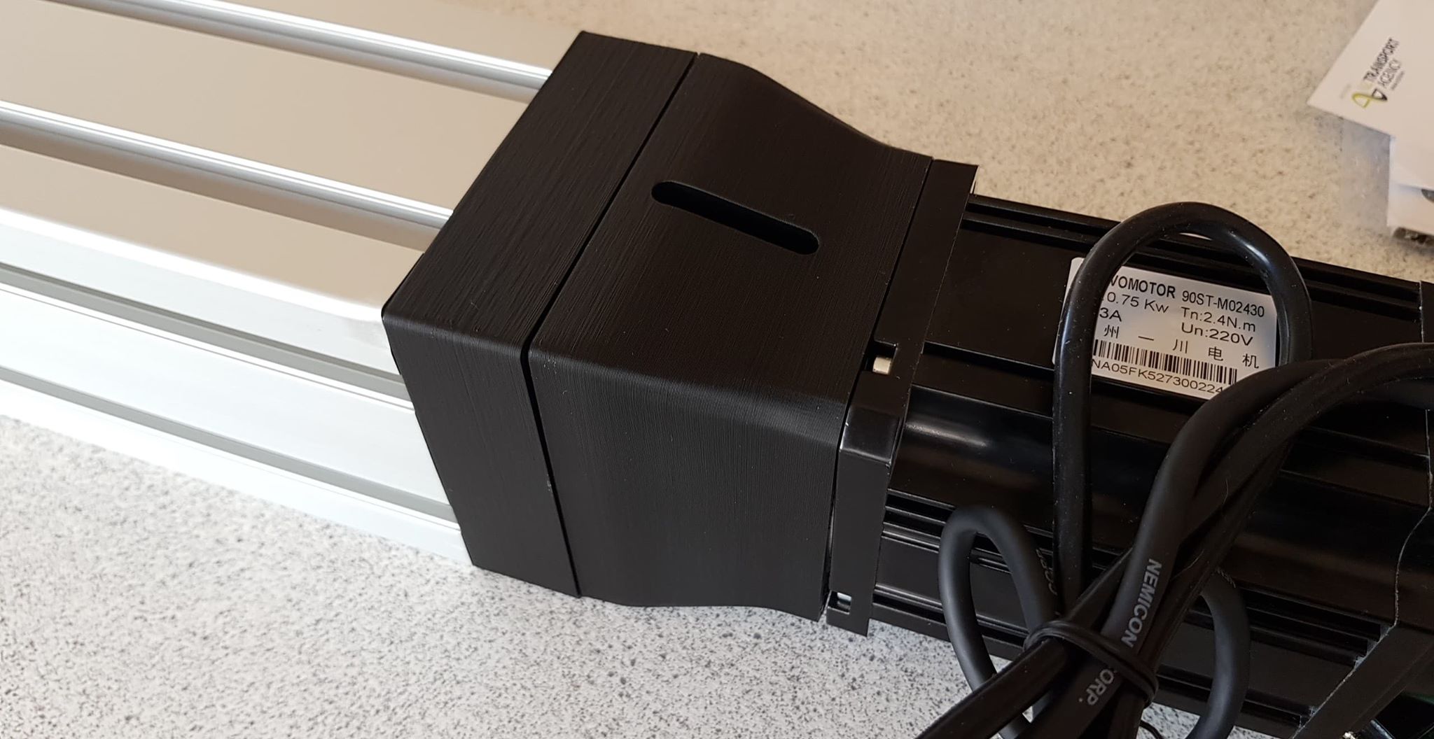
Done !
Edit 14/Jan Here’s a good video (in German, a video however tells 2000 words), at the 39min mark shows the the actuator in pieces so you get the idea.
Each actuator took about an hour a piece, looks can be deceiving, they are big and solid.


Really thanks for your sharing!
“Tip 2: The sliders – on my particular print settings they were too tight to fit in the extrusions. I needed to run a dremel down each groove here. I think I must be a unicorn on that front, hadn’t read any other reports of this.”
I have the exact same problem. I have tried with two different 3d-printers (Ender 3 & Prusa i3 MK3S) and my sliders also come out too large. I have calibrated both printers and the calibration cubes come out as good as they get. But the sliders are still too large. I am beginning to believe that 1) the STL:s are the cause of it or 2) That the design of the extrusion profiles have changed somewhat.
All other printed parts have a perfext fit.