Righto, had my initial fun with the SFX100 units so now it’s time to tidy up my mess.
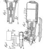
First stop the Arduino controller. Having this all exposed is not really the answer in a garage, it’s way too easy to accidentally pull a wire, and long term dust can’t be good for it. Originally I was going to design my own box to house the Arduino and DB25 connectors. However one question in the Owners Discord and what do you know? Problem solved by xhillb61 https://www.thingiverse.com/thing:3286372
A box especially designed for it.
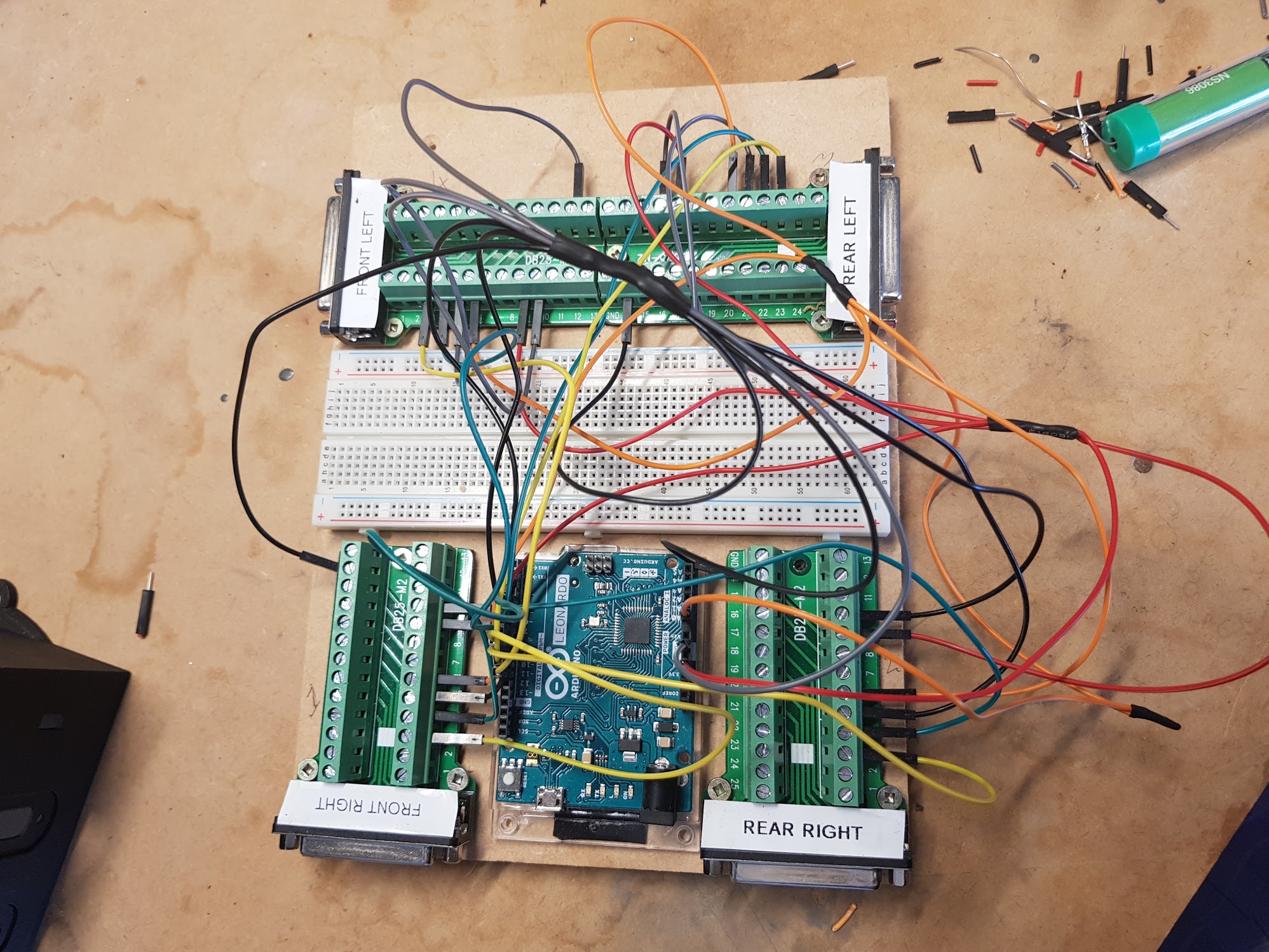
Note: I *strongly* suggest you start with the breadboard approach first – unless you’re perfect there’s a good chance of messing up a wire and if so your rig will not function properly, much easier to sort out on the breadboard than inside this box.
Step 1: Download .stl files and start printing. You know the drill by now 🙂
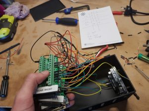
Step 2: Remove the breadboard from the wiring equation
In my case I chose to do the soldering/heatshrinking then test, then relocate it to the box. Which was good as I missed one of the pesky ground wires.
Step 3: Mount the Arduino
The screw holes don’t print terribly well and only one was in the right spot in my case. It did the job.
Learn from my mistake – I didn’t check the USB connection and mine was offset from the hole. There’s two ways of fixing it, the nice way and the ugly way – much easier to do the nice way now.
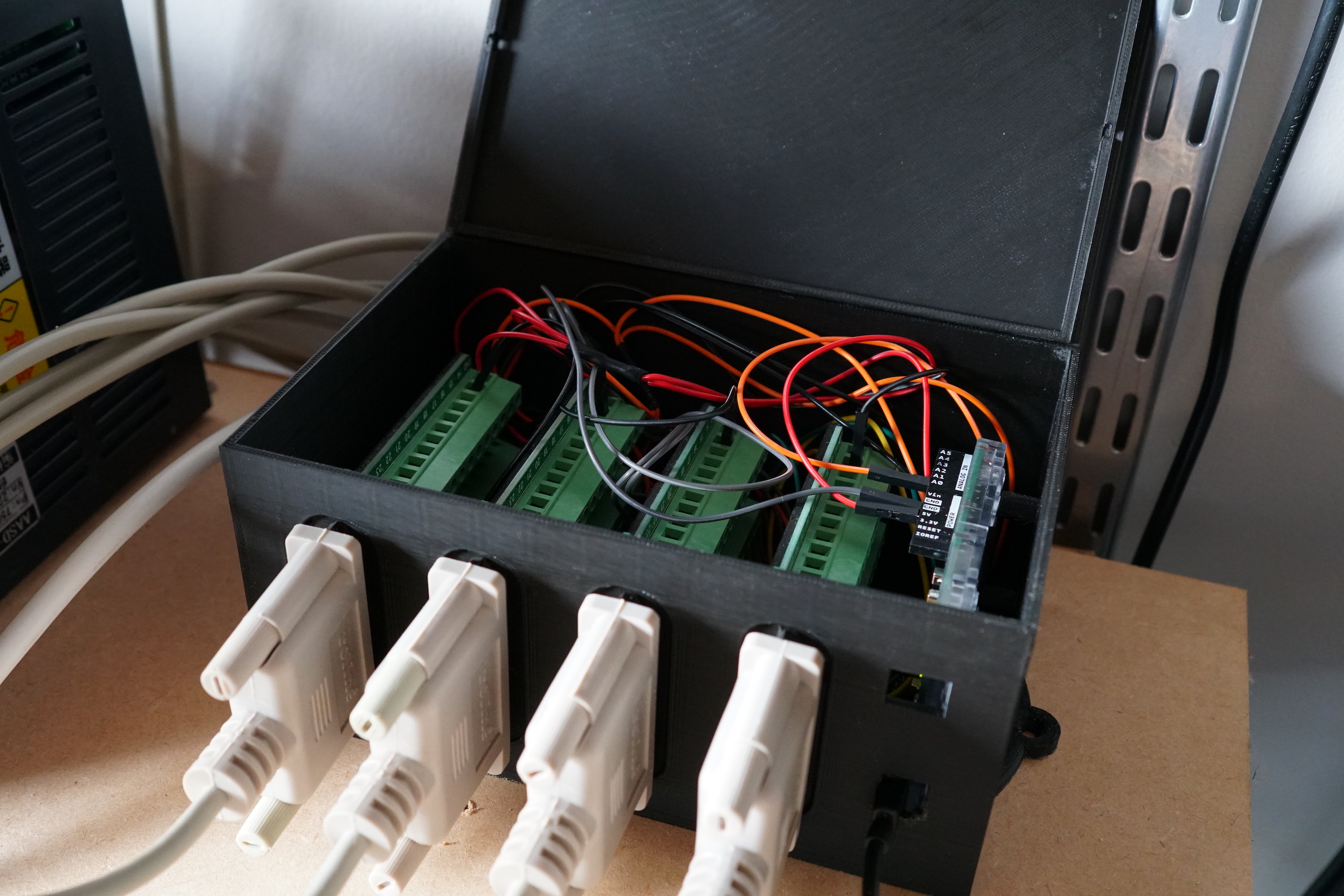
Step 4: Place in the DB25 connectors.
After a little testing what I found to work was I bent the connectors at right angles on the connector closest to the Ardunio. Then stacked the connectors all in my hand, wired in the yellow/green pairs to the arduino *first* then put in connector closet to Ardunio and worked outwards.
-
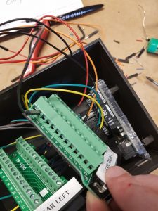
- Bend the first ones up at right angles
-
- Then hold in your hand and place in the box (note photo taken before the bend 90 degrees method)
Still, there will be lots of counting to 10 as it is very, very fiddly.
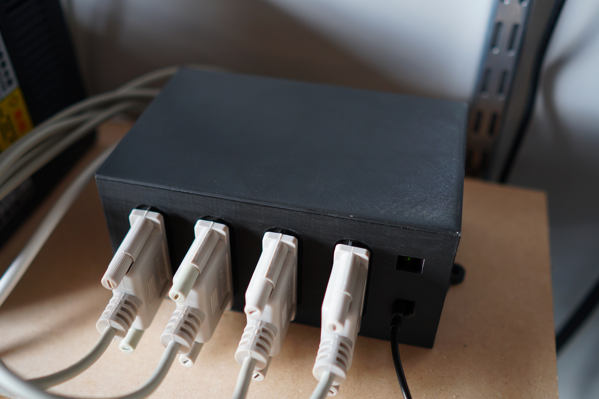
Step 5: Admire the tidy cables
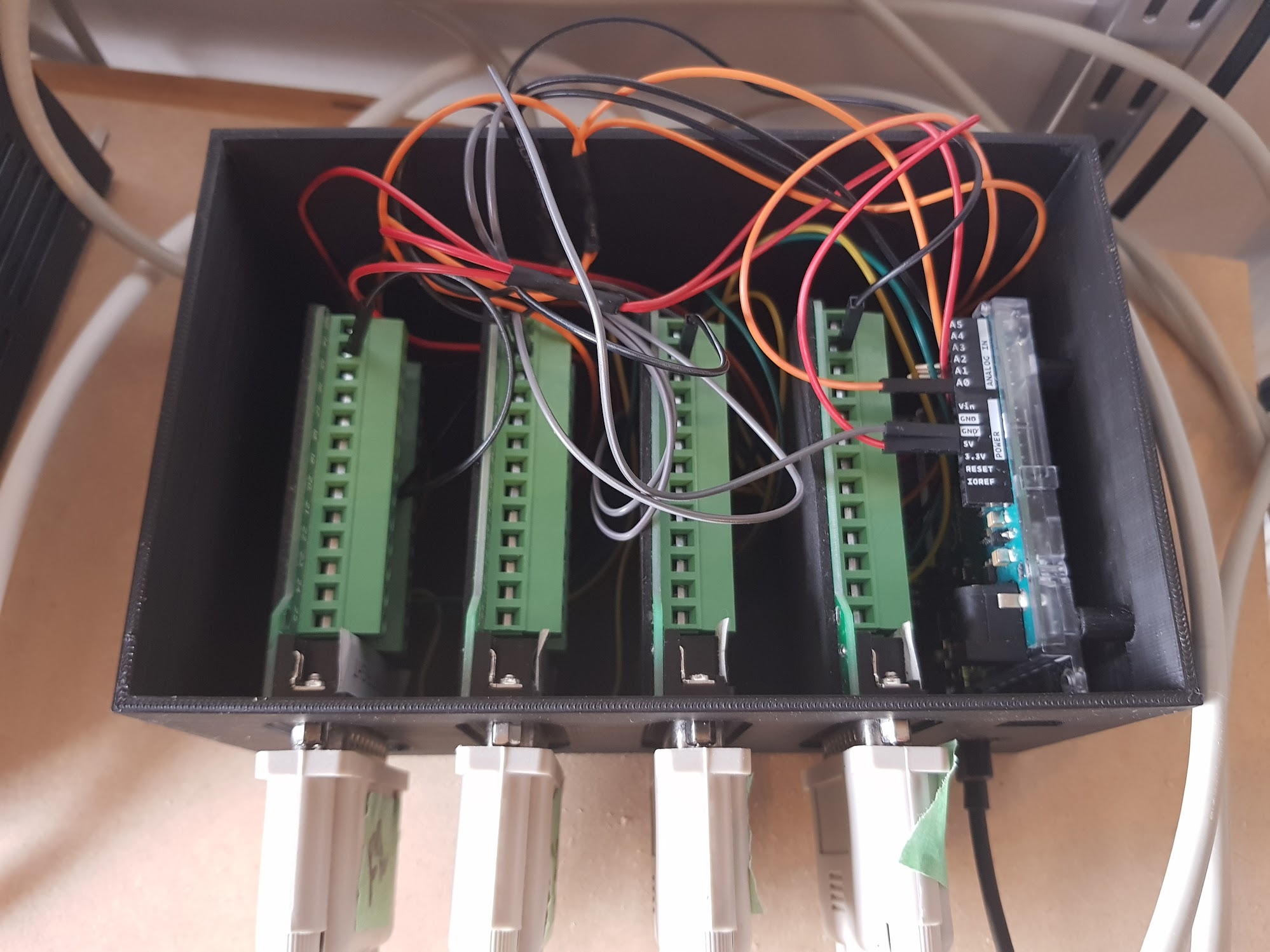
Step 6: Put the lid on, all done !