Many options present themselves for how to get a Sim Rig into your basement / garage / spare room. This is my relatively quick journey from ‘hmm I need to do something’ to ‘well that escalated!’.
Theory #1 – Alloy rig
The most appealing at first was the extruded aluminium style “8020” or “T-Slot” extrusions. With options from pre-packed kits to buying raw extrusions lengths that you cut and drill yourself – the options are endless. I coveted the alloy extrusion style, so I downloaded a free design tool designed a version using MayTec extrusion.
$1000 without shipping, without the monitor mounts …
Okay let’s take that off the table.
Theory #2 – MDF
Given a sheet of 1200*900 MDF was around the $33 mark. In one of my least planned projects I headed off to bunnings (Home Depot for the North Americans) with some gift cards in tow I hunter gathered some MDF, wood glue, and a couple of boxes of countersunk wood screws. A trip to a boyracer parts store netted a seat with guide runners (as a side note I’m constantly amazed by people on trademe selling second hand items for new prices) and super cheap suede covered steering wheel. Checkout “NZKW” on trademe for a bunch of options. The seat cost the princely sum of around $340 with runners and the wheel was all of $145.
Originally inspired by this guy http://lagnese.me/Hub/Home/Home.html I looked at his plans and layed everything out on the garage floor. The overall size of the rig became apparent, very apparent. Immediately I thought “I have to make it smaller”, as I had a real car that was at the workshop needing space also in the garage! The side pods I had no plans to put in transducers, amplifiers or other devices (or so I thought at the time, more on that in a later post) I just wanted a base chassis for stiffness of the wheel and seat. Changing the side pods from approx 250mm wide to around 75mm wide got the overall dimensions down considerably.I pulled out the track saw and got to work. (Side note: If you’re working with big heavy sheets of MDF/Ply these things are a god-send, you don’t need a $1500 Festool, this was a cheap $NZD400 saw with a Diablo 48T blade upgrade, good for occasional use).
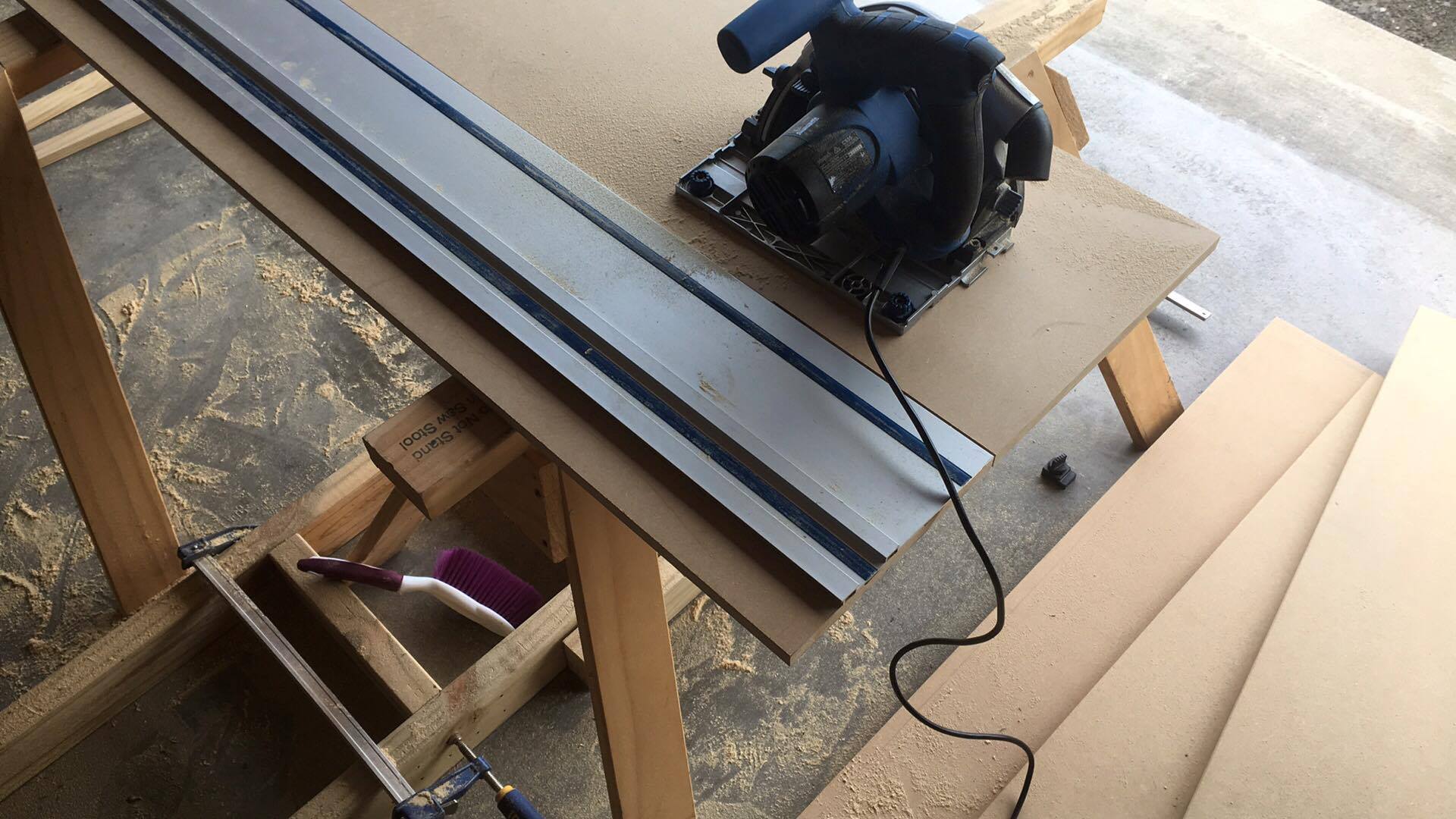
Scheppach Track Saw. Cheap. Cheerful and does the job. (note: buy a shop vac)
The sidepods were constructed of 2 panels being the MDF skins, with smaller batons of pine around the perimeter of the box panels. In a break from tradition I barely measured anything – just ensuring the main “tub” was square for the seat to move down and that was it. A lot of it was just laying out pieces and marking up with pencil by eye or doing a template from one side for the previous.
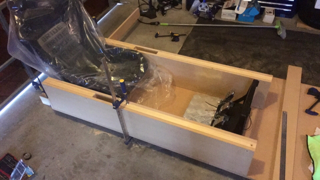
Getting the right dimensions before cutting the “floor pan”
After taking the plunge on the main floor pan I got the side pods glued up and screwed the floor, flipped it over and added 8 40mm casters (those are expensive!), at end of day 1 I was at a rolling chassis stage, with barely any measuring done.
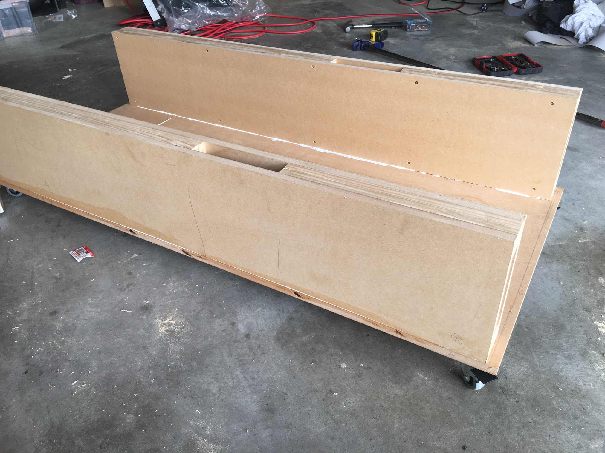
Rolling on wheels
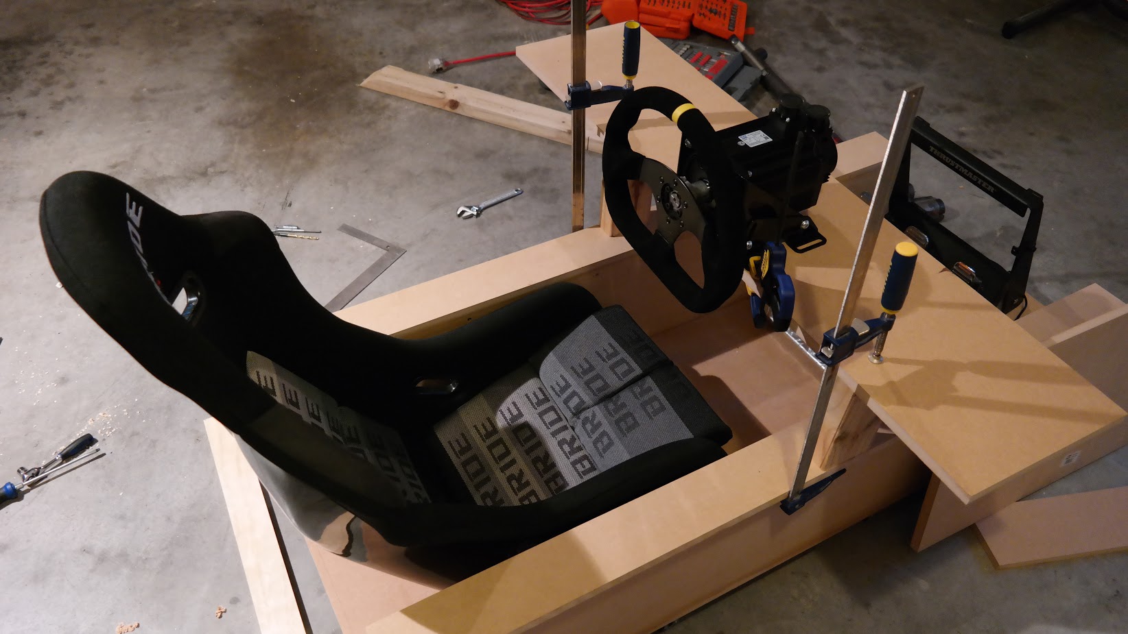
The rig quickly took shape – using clamps and bits of spare wood I mocked up positions of everything by eye to make sure we were on the money :
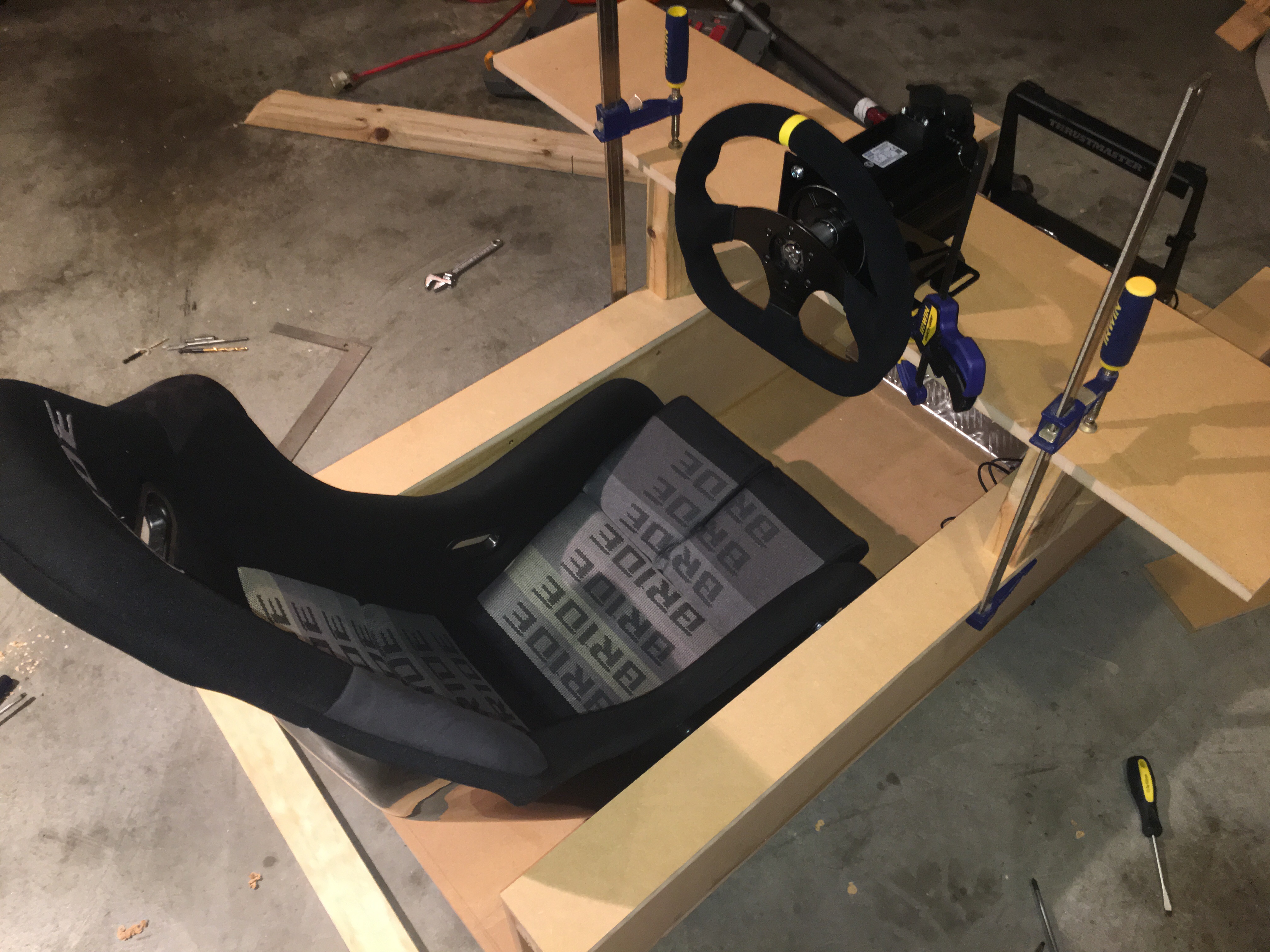
Gingerly mocked things up and tested out positions. Highly scientific
Once correct a break for a few days and then back into it. I’d planned to get the wheel mount CNC milled alloy for the wheel mount but again MDF seemed to be the best option. The actual mount itself is solid – having the high side tunnels gave a broad surface area that would handle the wheels torque. The wheel shelf doubles as a stand for the (currently single) display. In practise the mount has turned out to be incredibly solid.The minute that was in it was time to to get everything running in test :
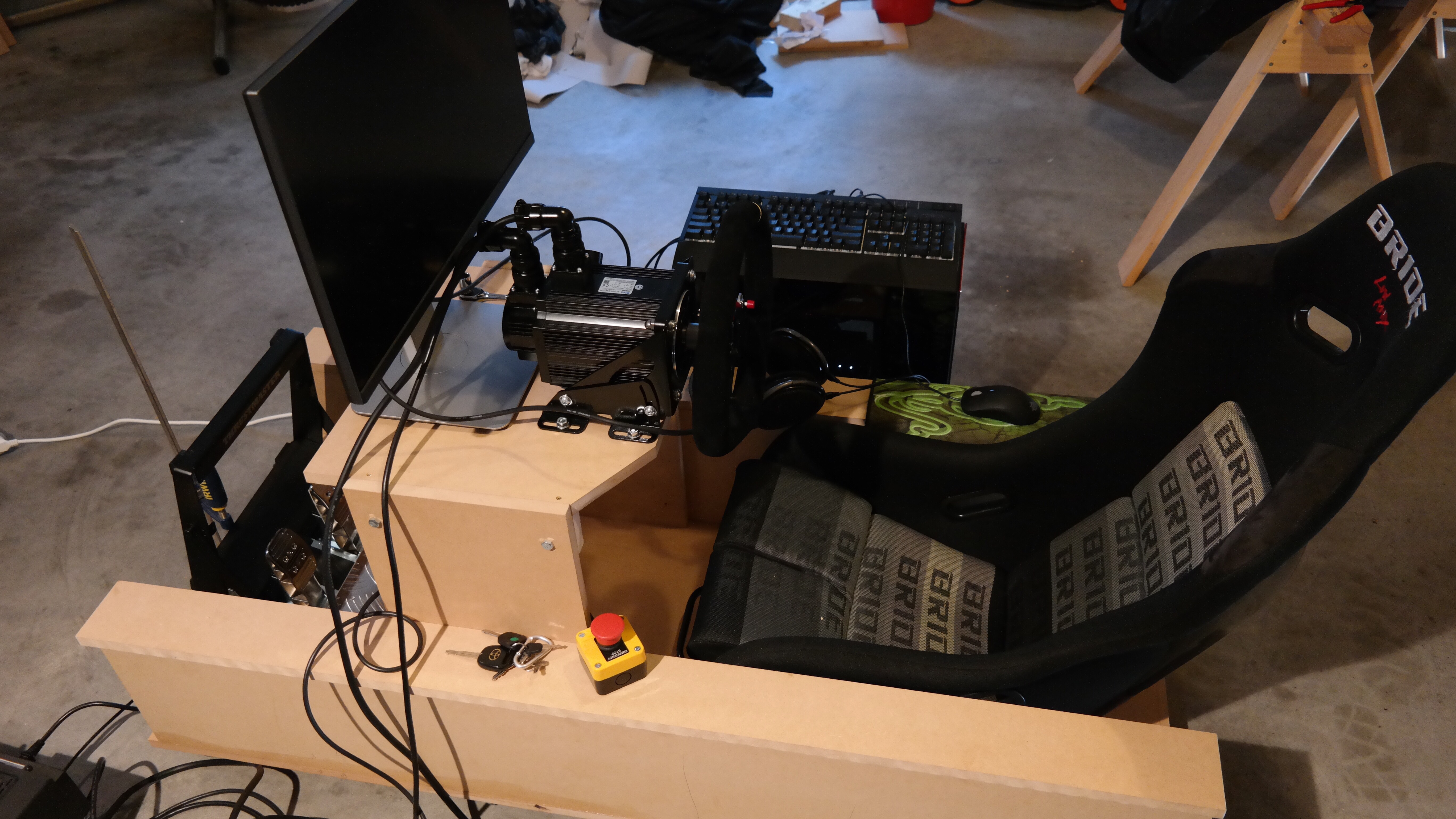
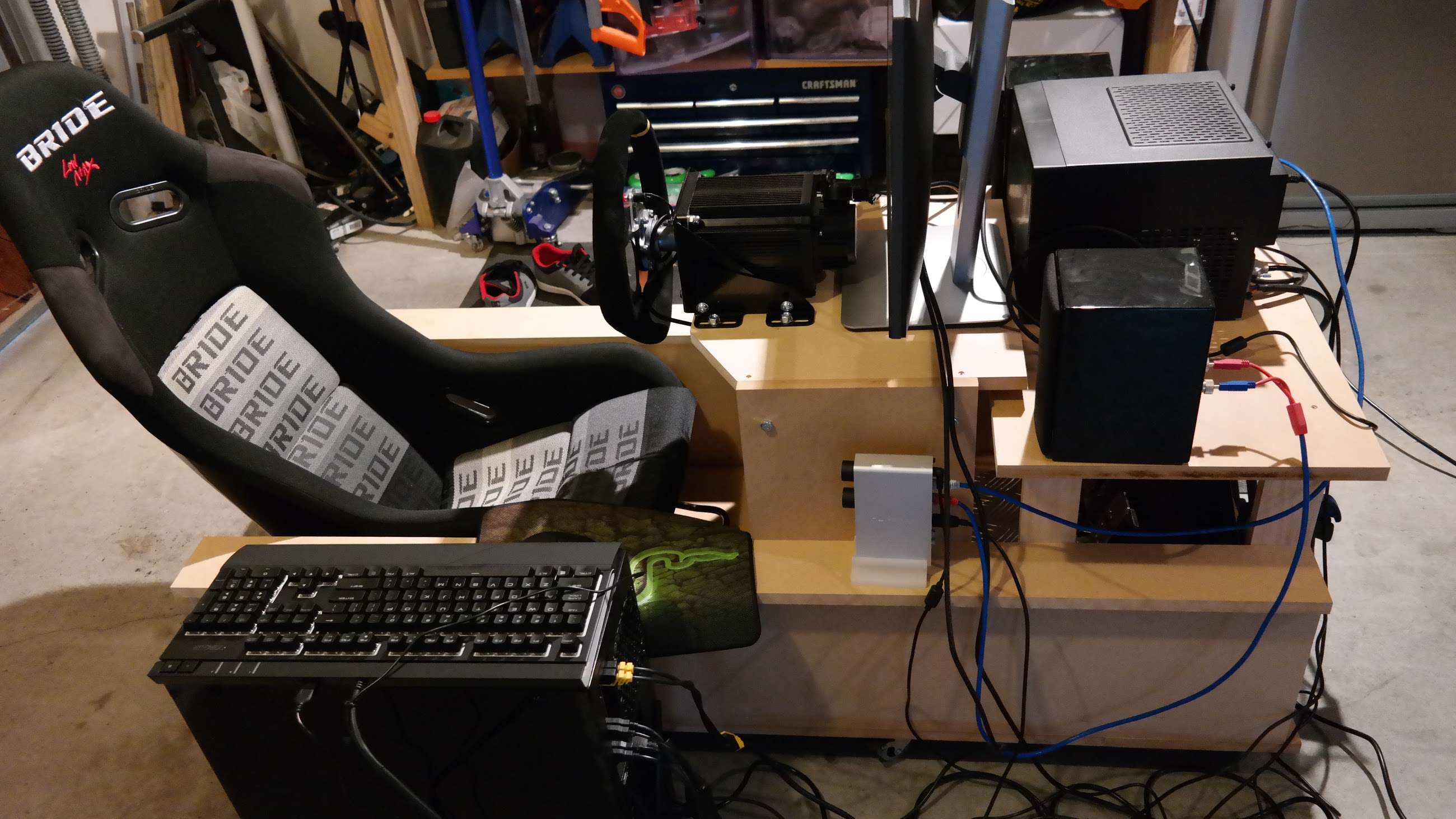
Cables everywhere. Safety first.
The result? Solid AF. 100% torque = insane. I seriously question why anyone would want to run at 100% or even worse get the big mige. On most cars I question anything above 60-70% torque settings as to how to realistic the max torque outputs are (short of the hairy shirt F1 days). A good measure is I get sore wrists on my real car after about 20-30mins on the track. Same deal on the Small Mige.
Testing over, with cables everywhere, drive controller on the ground it was time to tidy things up to make it a bit more friendly on the eyes. I built a second shelf behind the wheel stand (isolated from it) to house the SimuCube, button controller, and speakers.
Second shelf on :
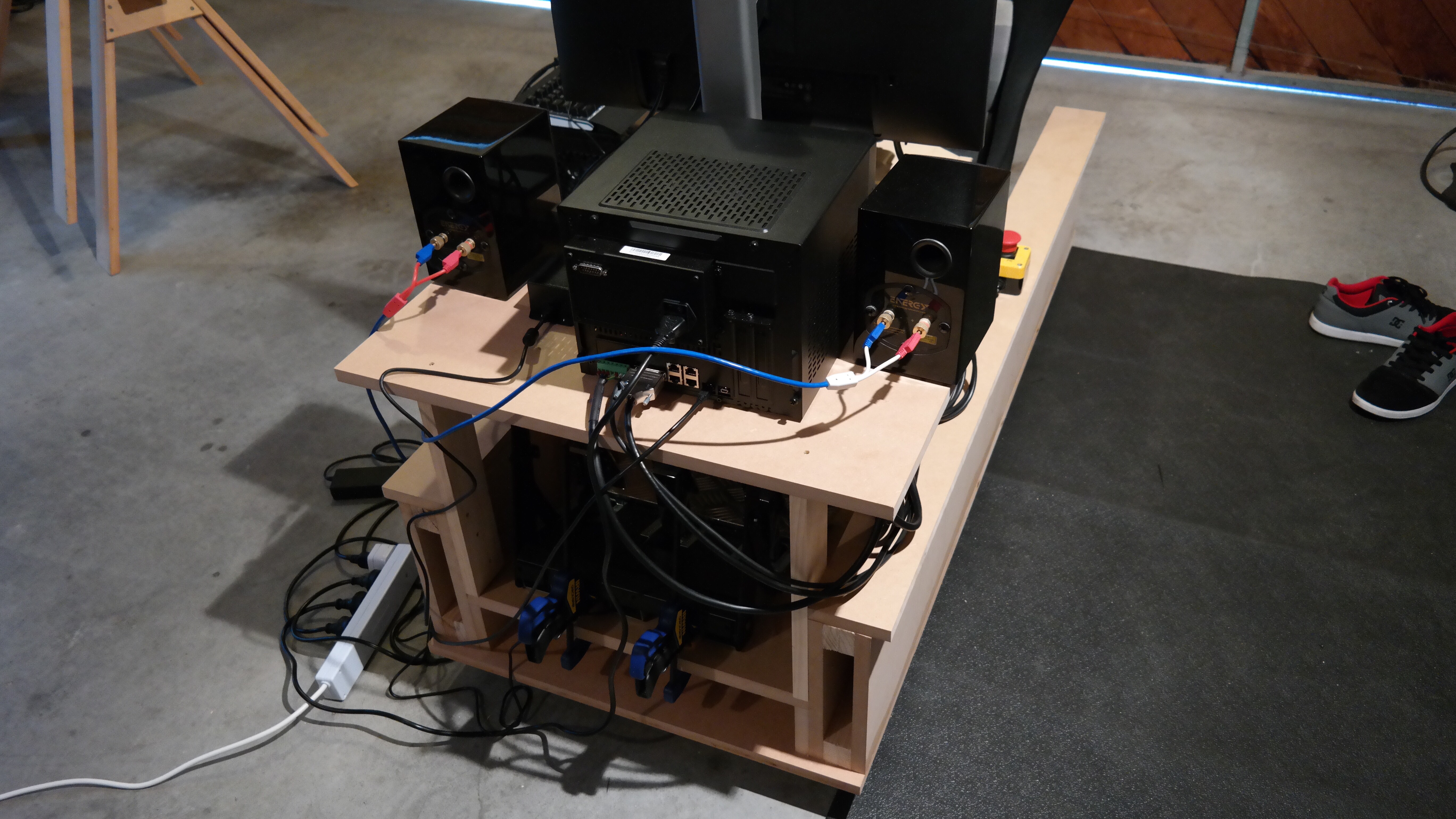
The cables just keep getting worse.
And of course I needed some gear shifting. The lead time on a SHH Shifter is a good solid month or two so I opted for a simple push button system to start off with. Leo Bodnar sells a nice little button box interface (arguably I could have also used the simucube I later realised..), fast shipping got it into my hands quickly. With some clear perspex and double sided tape temporary (and not the most beautiful mounts) were made. Poor quality push buttons are very apparent, the right one is a hair trigger, the left one is a hit and miss affair. Hmm something to sort in future. Maybe those $10 Knitter switches are worth it.
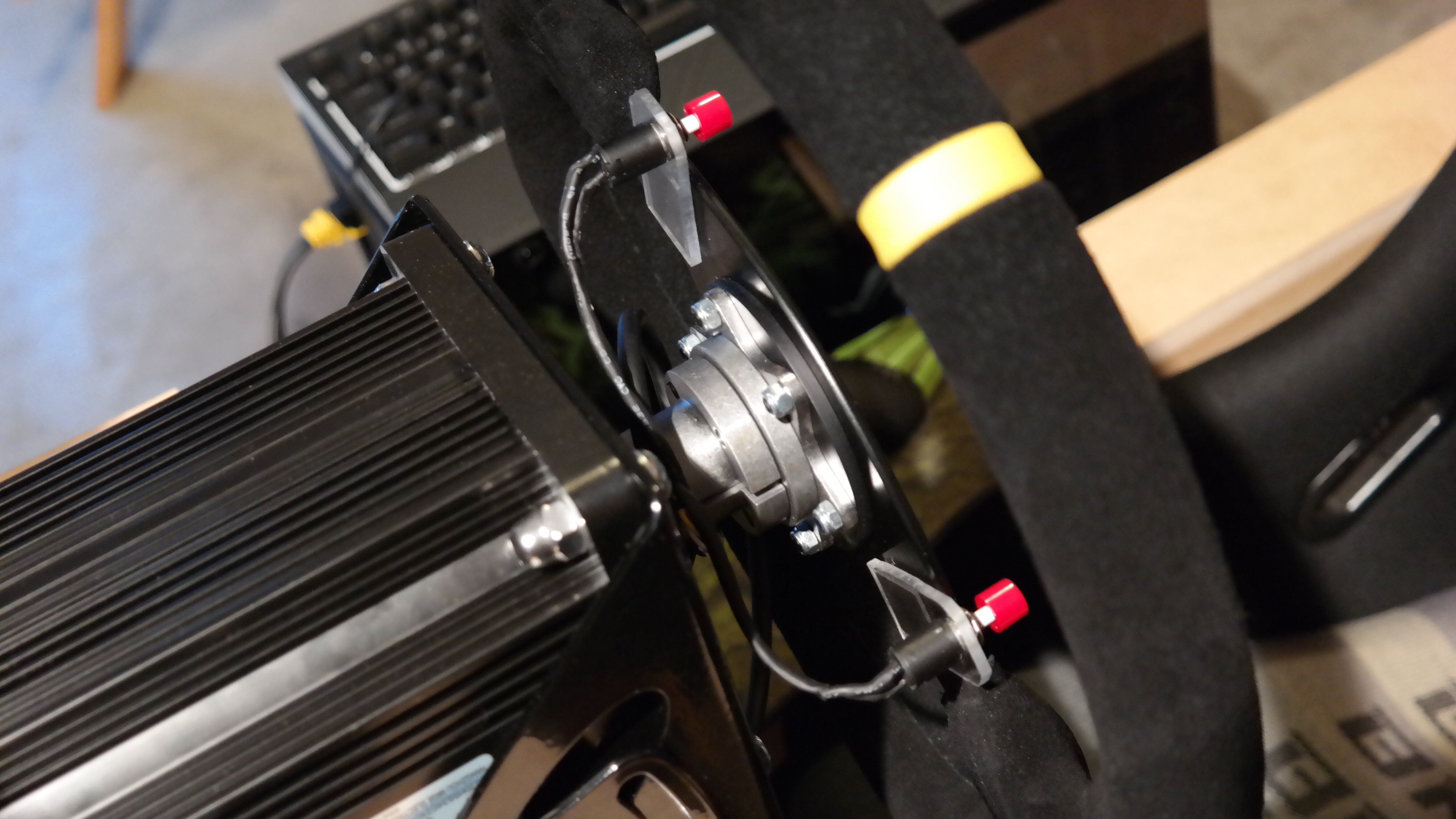
Temporary gearshift buttons. No measuring. The only concession to ergonomics was filing them so no cut fingers during opposite lock action.
So a couple of weeks of effort and $300 or so of materials and the rig was made. Not pretty but $1700 saved to put into a triple display later on.
The end of part 1 !


[…] the basics of the sim rig working, like any good project, upgrade time ensued pretty […]
Hi , do you still have the OSW setup ? were did you purchase the wheel setup from ? Thanks